Description
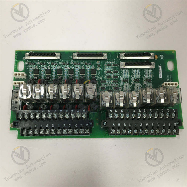
GE IS200TRTDH1C
I. Overview
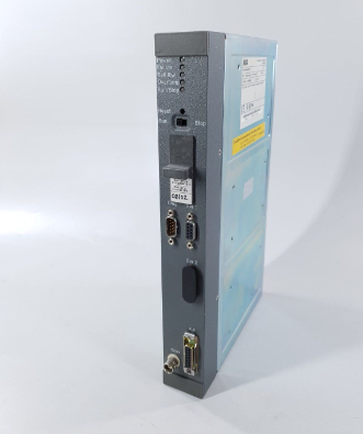
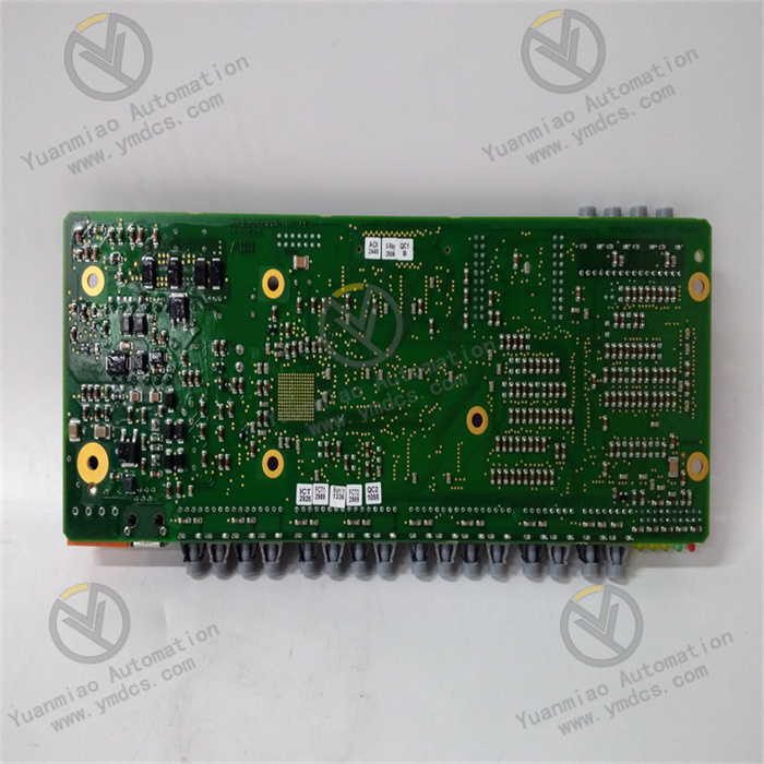
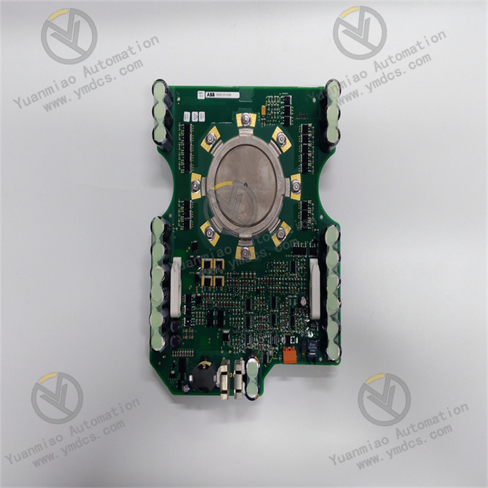
The GE IS200TRTDH1C is a high-precision Resistance Temperature Detector (RTD) input module, which serves as a core temperature acquisition component of the Mark VI steam turbine control system. Specifically designed for temperature monitoring of key components (such as bearing pad temperature, stator temperature, and bearing temperature) in large rotating machinery (including steam turbines, gas turbines, and generators), it undertakes critical tasks such as accurate acquisition of RTD sensor signals, signal conditioning, digital conversion, and fault diagnosis. As the "sensing core" of the temperature monitoring system, this module converts on-site temperature changes into precise digital signals through a dedicated RTD signal processing circuit, and uploads the signals to the control system for real-time monitoring and abnormal early warning, thereby providing core data support for the safe operation and fault prediction of equipment.
II. Technical Parameters
| Parameter Category | Specific Specifications | Detailed Description |
|---|---|---|
| Power Supply Parameters | Operating Power Input | DC 5V DC ±5% (logic power supply, from the system backplane bus), DC 24V DC ±10% (analog power supply, independent power supply); Logic power supply fluctuation range: 4.75V~5.25V, Analog power supply fluctuation range: 21.6V~26.4V; Equipped with reverse power connection protection and overvoltage protection functions |
| Power Consumption Indicator | Logic power consumption ≤ 4W; Analog power consumption ≤ 8W; Total power consumption under full load operation ≤ 12W; Standby power consumption ≤ 2W | |
| RTD Acquisition Parameters | Number of Input Channels | 16 differential RTD input channels, adopting single-channel independent isolation and conditioning design |
| Supported Sensor Types | Pt100 (385Ω/℃), Pt1000 (385Ω/℃), Cu50 (42.8Ω/℃), Cu100 (42.8Ω/℃); Supports 2-wire, 3-wire, and 4-wire connection modes, with independent configuration for each channel | |
| Measurement Range and Accuracy | Pt100/Pt1000: -200℃~600℃, accuracy ±0.05% FS; Cu50/Cu100: -50℃~150℃, accuracy ±0.1% FS; Equipped with an 18-bit high-precision ADC chip | |
| Sampling Rate | Maximum sampling rate per channel: 100Hz; Total sampling rate ≥800Hz during multi-channel polling sampling; Channel switching time ≤ 5μs | |
| Lead Resistance Compensation | Supports automatic lead resistance compensation for 3-wire/4-wire systems, compensation range: 0~10Ω per wire; Manual compensation setting supported for 2-wire systems | |
| Signal Processing Parameters | Filter Function | Built-in hardware RC filter (switchable cutoff frequency: 50Hz/60Hz) + programmable digital filter (adjustable filter time constant: 1ms~1000ms) |
| Isolation Level | Isolation voltage between channels ≥ 1500V AC (rms), Isolation voltage between channels and power supply/ground ≥ 2500V AC (rms), in compliance with IEC 61131-2 standard | |
| Communication and Redundancy Parameters | Communication Interface | Communicates with the controller via the Mark VI system backplane bus, bus rate: 1Mbps, data transmission delay ≤ 8μs; Supports 1 RS485 debugging interface |
| Redundancy Design | Supports 1+1 hot redundancy configuration, with master and backup modules synchronizing acquisition data and configuration parameters in real time; Redundancy switching time ≤ 50ms | |
| Environmental Parameters | Temperature and Humidity Range | Operating temperature: 0℃ ~ 65℃; Storage temperature: -40℃ ~ 85℃; Relative humidity: 5% ~ 95% (no condensation) |
| Anti-interference and Protection | Complies with IEC 61000-4 anti-interference standard, ESD contact discharge ±8kV, air discharge ±15kV, surge immunity ±2kV, burst immunity ±2kV; Protection class IP20, suitable for installation in control cabinets | |
| Physical Parameters | Dimensions and Installation | 220mm × 180mm × 100mm (length × width × height); Installed via DIN 35mm standard guide rail or fixed with screws; Recommended module spacing ≥ 30mm to ensure heat dissipation |
III. Functional Features
1. Compatibility with Multiple RTD Types, Diverse Acquisition Scenarios
2. High-Precision Acquisition and Compensation, Accurate and Reliable Data
3. Enhanced Anti-Interference and Redundancy Design, Adaptation to Severe Working Conditions
4. Comprehensive Fault Diagnosis and Alarm, Efficient Operation and Maintenance
5. Flexible Configuration and Intelligent Operation and Maintenance, Reduced Maintenance Costs
6. High Compatibility and Data Traceability, Facilitating Intelligent Management
IV. Common Faults and Solutions
| Common Faults | Possible Causes | Solutions |
|---|---|---|
| Module fails to power on, power indicator is off | 1. System backplane bus fault (logic power supply not provided); 2. Loose connection between the module and the backplane bus; 3. Loose wiring or abnormal voltage of the analog power supply; 4. Module power circuit fault | 1. Check the output of the Mark VI system power module to ensure normal 5V power supply on the backplane bus; 2. Power off, reinsert the module to ensure a secure connection with the backplane bus; 3. Check the wiring of the analog power supply (24V DC) and measure the voltage; repair the power supply circuit or install a voltage regulator if abnormal; 4. Test with a spare module; if the power circuit is confirmed faulty, return the module for repair |
| Significant deviation in acquired data | 1. Incorrect sensor wiring (e.g., reversed positive and negative poles in 3-wire system, loose leads); 2. Incorrect configuration of channel sensor type or connection mode; 3. Lead resistance compensation not enabled or incorrect compensation parameters; 4. Module not calibrated or calibration expired; 5. Sensor aging or damage | 1. Recheck the wiring diagram and rewire; fasten the lead terminals; 2. Verify the channel configuration via the configuration software to ensure consistency with the sensor type and connection mode; 3. Enable the automatic compensation function (for 3-wire/4-wire systems) or manually set compensation parameters (for 2-wire systems); 4. Recalibrate the channel with a standard resistance box; 5. Replace the sensor and recalibrate |
| "Sensor fault" alarm for a specific channel | 1. Sensor open circuit or loose wiring; 2. Sensor short circuit; 3. Lead resistance exceeding the compensation range (>10Ω per wire); 4. Fault in the channel signal conditioning circuit | 1. Check the sensor wiring, fasten terminals, and test the line continuity; 2. Measure the sensor resistance with a multimeter to eliminate short-circuit faults; 3. Replace with thicker wires or shorten the transmission distance to ensure lead resistance ≤10Ω per wire; 4. Connect the sensor to a spare channel for testing; if the circuit is confirmed faulty, return the module for repair |
| Frequent fluctuations in acquired data | 1. Severe on-site electromagnetic interference (e.g., interference from the steam turbine excitation system); 2. Sensor not grounded or poorly grounded; 3. Excessively small filter parameter settings; 4. Poor contact of wiring due to sensor vibration | 1. Identify on-site interference sources; use shielded twisted-pair cables for sensor wiring and ensure reliable grounding; keep away from high-voltage cables; 2. Ensure single-point grounding of the sensor and module, with a grounding resistance ≤4Ω; 3. Increase the digital filter time constant (50~100ms recommended) or switch the hardware filter frequency; 4. Reinforce the sensor wiring terminals and use anti-vibration terminals |
| Redundant module switching failure, master-backup asynchrony | 1. Loose wiring of the master-backup module synchronization link; 2. Inconsistent configuration parameters between master and backup modules; 3. Incompatible firmware versions of master and backup modules; 4. Module hardware fault causing loss of synchronization signals | 1. Check the wiring of the synchronization link, fasten terminals, and replace damaged cables; 2. Synchronize the parameters of the master and backup modules via the configuration software to ensure consistency; 3. Upgrade the firmware of the master and backup modules to the same version, referring to the GE official compatibility list; 4. Test with a spare module; if the hardware is confirmed faulty, return the module for repair |