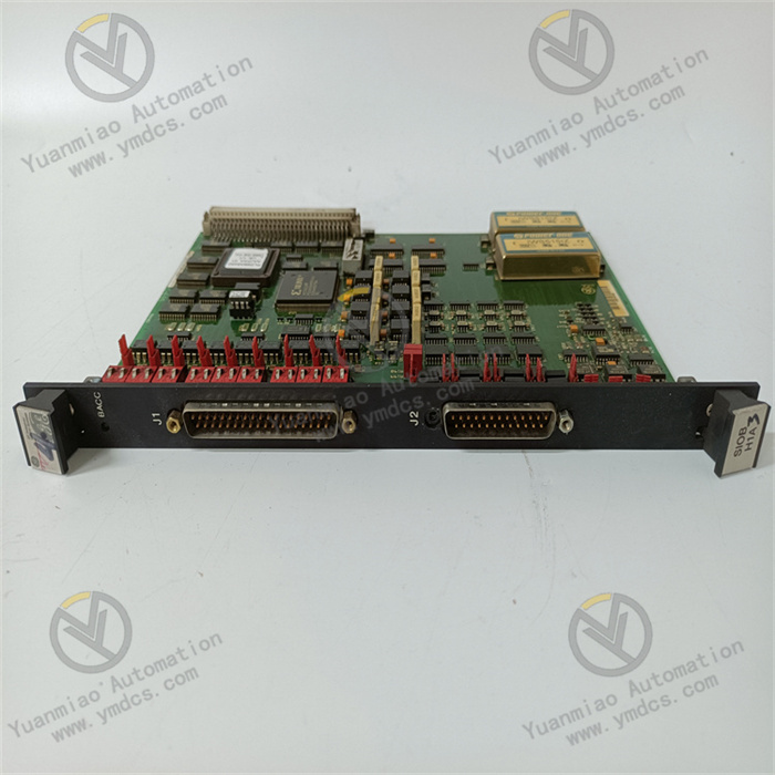
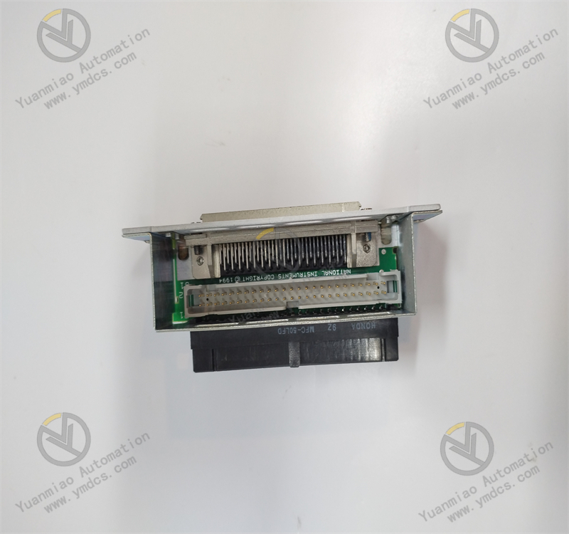
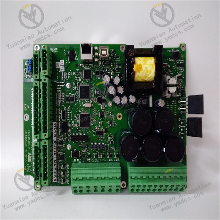
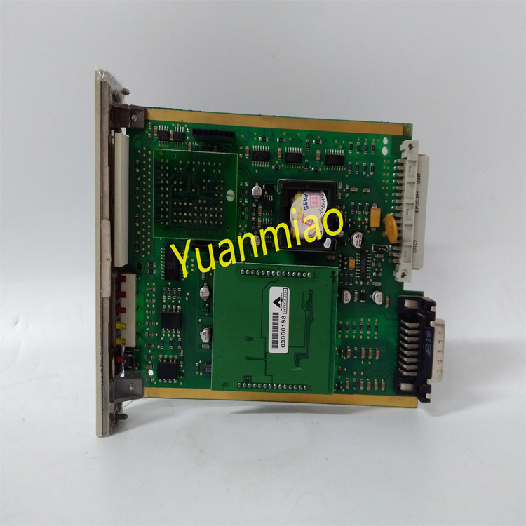
Description
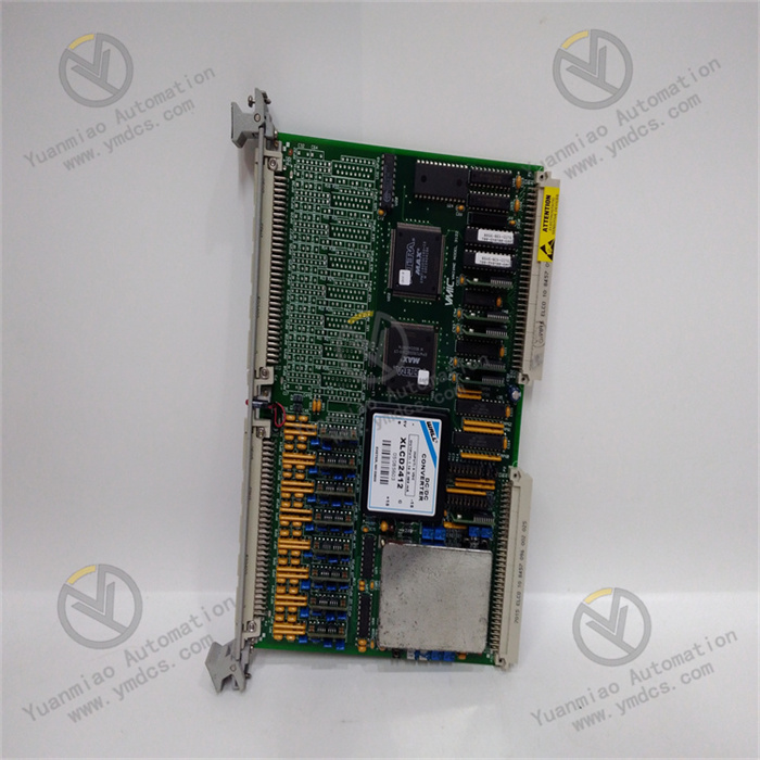
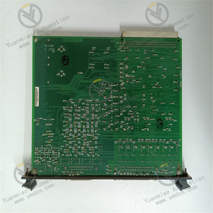
GE DS200LDCCH1AMA
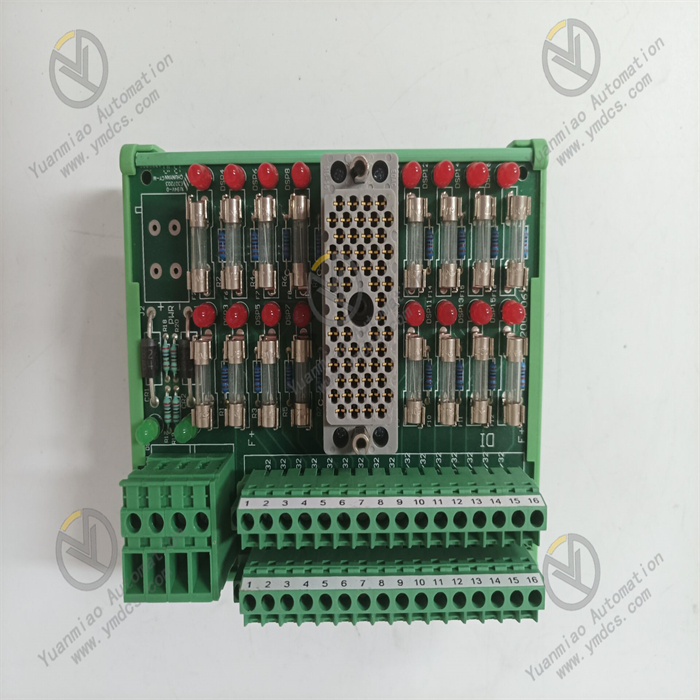
GE DS200LDCCH1AMA is a digital input/output (I/O) module positioned as the "Core Unit for Centralized Processing of Digital Signals in Steam Turbine Auxiliary Control Systems". It is mainly applied in steam turbine control systems in fields such as thermal power generation, nuclear power generation, and industrial drives. Undertaking key tasks including status collection of auxiliary equipment, output of control commands, and feedback of fault signals, it provides reliable hardware support for signal interaction between auxiliary control loops (e.g., steam turbine lubricating oil system, seal oil system, and condensate system) and the main control system.
Deeply adapted to the Mark VI control system architecture, this module adopts a high-density digital I/O channel design, photoelectric isolation technology, and a redundant fault-tolerance mechanism. It can directly connect to auxiliary steam turbine equipment such as contactors, solenoid valves, pressure switches, and temperature switches. Without the need for additional signal conversion modules, it realizes full-link signal processing covering "digital input collection - signal isolation processing - system communication upload" and "control command reception - isolation amplification - digital output execution". Its core advantages lie in high channel density, excellent isolation performance, strong anti-interference capability, and seamless compatibility with the Mark VI system. It is suitable for auxiliary control scenarios of 300MW-1000MW thermal power steam turbines, nuclear power conventional island steam turbines, and industrial drive steam turbines. Capable of long-term stable operation in harsh conditions such as a wide temperature range (-20℃ to 65℃), strong electromagnetic interference, and high vibration, it meets the requirements of the steam turbine industry for reliability, real-time performance, and safety in digital signal processing.
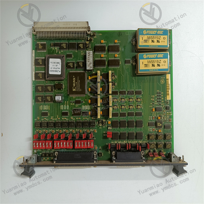
The module adopts the dedicated VME bus architecture of the Mark VI control system and can be directly embedded in a standard VME rack. Mechanical fixation and electrical connection are achieved through high-density bus connectors, with no additional adapter components required during installation and access. Physical installation and system integration can be completed within 30 minutes. After access, the ToolboxST configuration software of the Mark VI system can automatically identify the module model, hardware version, and channel configuration information. Engineers can complete the functional configuration of DI/DO channels (e.g., input filtering time setting, output mode selection, fault diagnosis threshold configuration), logical association, and online debugging through a graphical interface, without the need to write underlying driver programs. The data transmission adopts a synchronous communication mechanism: the cycle of uploading digital input signals to the main controller is ≤1ms, and the delay of output commands issued by the main controller is ≤0.5ms, ensuring real-time synchronization between the status of auxiliary equipment and the main control system. For example, when the lubricating oil pressure switch is activated, the module can upload the signal to the main controller within 1ms, and the main controller can issue a solenoid valve activation command within 2ms to achieve rapid response.
It integrates 32 digital input channels and 16 digital output channels, adopting a grouped design (4 groups of 8 channels for DI, 4 groups of 4 channels for DO). It can centrally process various types of digital signals in the steam turbine auxiliary control system, significantly reducing the number of modules used and the rack space occupied. The digital input channels support dry contact and wet contact mode switching, which can be configured through terminal block jumpers. The dry contact mode can directly access passive contact signals such as pressure switches and temperature switches, while the wet contact mode can access active signals such as PLCs and sensors. The output channels support two modes: relay and transistor. The relay mode is suitable for high-power executive components such as solenoid valves and contactors, and the transistor mode is suitable for low-power loads such as indicator lights and small relays, without the need for additional power amplification modules. Each group of channels is equipped with independent status indicator lights, which can intuitively display the on-off status and fault status of the channels. Engineers can quickly judge the working status of the channels through the indicator lights. For example, a steady light of the DI channel indicator means normal signal input, and a flashing light means a channel fault.
It adopts a three-level isolation design of "channel-level - group-level - system-level". The digital input and output channels adopt photoelectric isolation technology with the system logic circuit, with an isolation voltage of 2500V AC, which effectively blocks strong electromagnetic interference generated by high-voltage equipment and frequency converters in the steam turbine room from entering the core circuit of the system. The isolation voltage between channels is 1000V AC, avoiding signal crosstalk between different channels. For example, the switching action of the DO channel will not interfere with the signal collection of the DI channel. The module has excellent electromagnetic compatibility performance, with a common mode rejection ratio of ≥120dB and a differential mode rejection ratio of ≥100dB. It has passed the certification of IEC 61000-4-2/3/4/5 and other series of electromagnetic compatibility standards, and can resist various interferences such as electrostatic discharge, radio frequency interference, and electrical fast transient bursts. The housing is made of die-cast aluminum alloy with an anti-static and anti-corrosion coating, and the internal circuit board is treated with three-proof paint, which further enhances anti-interference and anti-corrosion capabilities, ensuring stable operation in the steam turbine auxiliary control cabinet with strong electromagnetic interference and high humidity.
It integrates full-dimensional fault diagnosis functions at the channel level and module level. The digital input channels support short-circuit, open-circuit, and overvoltage diagnosis. When a channel short-circuit is detected, the module immediately cuts off the input circuit of the channel and triggers an alarm. The output channels are equipped with overcurrent protection (transistor output) and contact arc suppression (relay output), which can automatically limit current in case of short-circuit faults and resume normal output after the fault is eliminated. The module is equipped with 16 channel status indicator lights, 4 group fault indicator lights, and 2 system status indicator lights, which can intuitively display the working status of each channel, group-level faults, and system communication status. Fault information (fault channel number, fault type, occurrence time) is uploaded to the main controller in real-time through the VME bus, linking with HMI interface pop-up alarms and storing fault logs (capable of storing 200 timestamped records). Engineers can query fault details through the ToolboxST software, and complete fault location without disassembling the module on-site, reducing fault troubleshooting time by more than 80%.
It supports module-level 1:1 redundant backup configuration. The main and backup modules realize real-time data synchronization through the VME bus. When the main module has a power fault, communication fault, or channel fault, the redundant logic unit can automatically switch to the backup module within 2ms, ensuring the continuity of digital signal collection and output without data loss or control interruption. The redundant status is intuitively displayed through the "main/backup status indicator light" on the module: the indicator light is steady on when the main module is working, flashes when the backup module is on standby, and flashes quickly to indicate switching. The ToolboxST software can monitor the working status of the main and backup modules and the consistency of channel data in real-time. When there is a deviation in the data of the main and backup channels, an alarm is triggered immediately, facilitating engineers to troubleshoot problems in a timely manner. This redundant design is particularly suitable for critical auxiliary control loops such as steam turbine lubricating oil pump control and seal oil system control, providing double guarantees for the safe operation of the unit.
Industrial-grade wide-temperature components are selected. Key components such as core chips, relays, and transistors are all industrial-grade products with an operating temperature range covering -20℃ to 65℃, which can adapt to the high-temperature environment (up to 60℃ without air conditioning) in the steam turbine room in summer and low-temperature environment in winter. The module adopts a natural heat dissipation + high-density heat sink design. Core heating components (relays, power tubes) are closely attached to the heat sink, and the housing is designed with heat dissipation grooves to enhance heat exchange efficiency. When operating at full load in a high-temperature environment of 65℃, the core temperature of the module is still ≤80℃, without the need for additional cooling fans, avoiding module damage caused by fan faults. The vibration resistance level reaches 2g (10-2000Hz). The overall rigidity of the module is enhanced through structural optimization design, and anti-vibration terminals and bus connectors are adopted, which can be installed in the auxiliary control cabinet near the steam turbine to resist the high-frequency vibration generated by the unit operation. The Mean Time Between Failures (MTBF) reaches 800,000 hours, and the service life is ≥15 years, fully meeting the requirements of the steam turbine industry for long-term reliability of equipment.
![]()


