Description
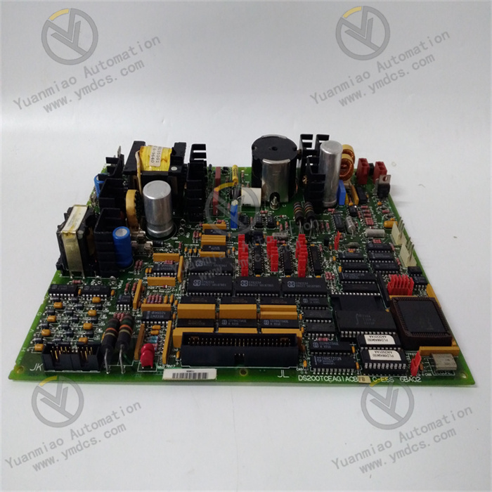
GE DS200UPLAG1BDA
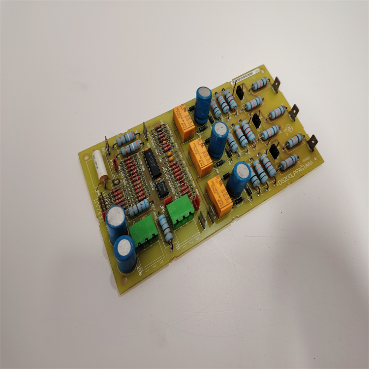
The GE DS200UPLAG1BDA is a high-performance redundant power supply module specifically developed by General Electric (GE) for core power supply scenarios in industrial control systems. It belongs to the power supply component family of the GE Mark VIe series steam turbine generator control system, and its core positioning is a "highly reliable power supply center" for steam turbine generator control systems in thermal power plants and nuclear power plants, as well as large-scale industrial PLC systems. Integrating GE's core technological accumulation in the field of industrial power supplies, this module adopts a dual-channel redundancy architecture, a wide-range input regulation design, and a multi-layer protection reinforcement scheme. It undertakes key tasks such as stable power supply, voltage regulation, redundancy switching, and fault early warning for critical equipment in industrial control systems, including core controllers, I/O modules, and monitoring modules. Meanwhile, it features deep compatibility with GE Mark VIe controllers, Power Distribution Units (PDUs), and system monitoring software, ensuring high stability and high reliability of the power supply system from electrical energy input to load output.
As a core redundant power supply module of the Mark VIe series, the DS200UPLAG1BDA is highly compatible with GE DS200PDIAH1A power distribution boards, DS200PWRBH1B power backplanes, and system monitoring modules. It can be directly embedded into standard cabinets of the Mark VIe control system, enabling real-time communication and status feedback with the system via the backplane bus. Full-process operations such as input/output parameter calibration, redundancy mode setting, and protection threshold configuration can be completed without additional voltage stabilization equipment. It is widely used in key fields such as power supply for Mark VIe control systems of steam turbine generators in thermal power plants, core power supply for safety-level DCS systems in nuclear power plants, power support for large chemical PLC control systems, and power supply for rolling mill control systems in iron and steel plants. It provides uninterrupted power support for core processes such as controller command operation, I/O module data transmission, and monitoring module signal acquisition. It is a key core component for preventing unplanned shutdowns of control systems due to power supply interruptions and improving system operational safety. The module features dual-channel redundant power supply, wide-range input adaptation, multi-fault protection, precise voltage regulation, and intelligent status monitoring. It can adapt to harsh industrial site conditions such as voltage fluctuations, electromagnetic interference, high temperature, and high humidity, significantly enhancing the stability and fault tolerance of power supply systems in industrial control systems.
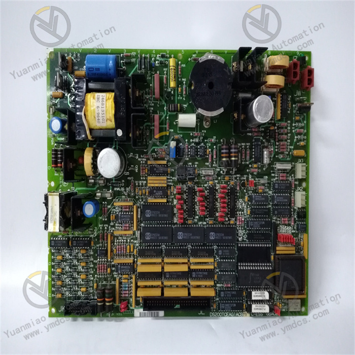
It adopts a redundant architecture with dual independent inputs and parallel outputs. The two input channels can be connected to different commercial power circuits or UPS power supplies respectively, realizing a highly reliable power supply guarantee of "seamless switching to the other channel when one channel fails". The redundancy switching time is ≤1ms, which is much lower than the power supply interruption tolerance threshold of core equipment in industrial control systems (usually ≥10ms). This ensures that when the power supply of a single input channel is suddenly cut off, the power supply to the load equipment remains uninterrupted, avoiding serious consequences such as controller program crash and I/O data loss. The dual input channels support load sharing function with a sharing accuracy of ±5%. During normal operation, each of the two power supply channels bears 50% of the load, effectively reducing the operating pressure on a single power supply channel and extending the overall service life of the module. In the power supply scenario of DCS systems in nuclear power plants, the two input channels are connected to the on-site commercial power supply and the emergency diesel generator power supply respectively. Even if the commercial power supply is interrupted, the redundancy switching can ensure continuous power supply during the interval before the diesel generator starts, meeting the power supply requirements of nuclear safety-level equipment.
It supports a wide input range of 85-264VAC and is compatible with two mainstream industrial power supply specifications (110VAC and 220VAC). It can adapt to power supply systems in different regions and scenarios without replacing the module, making it particularly suitable for industrial sites with large grid voltage fluctuations (such as iron and steel plants and metallurgical plants). When the input voltage fluctuates by ±20%, the output voltage fluctuation is ≤±0.2%. Combined with the dynamic voltage compensation function, when the load changes suddenly from 5% to 100%, the output voltage recovery time is ≤50μs and the fluctuation range is ≤±0.3%, providing a stable 24VDC power supply for equipment with high power supply quality requirements such as GE Mark VIe controllers. It supports fine adjustment of the output voltage within the range of 23.5-24.5VDC. The output voltage can be precisely adjusted according to the actual needs of the load equipment through the front-panel buttons or monitoring software, further improving the power supply matching degree. With a conversion efficiency of ≥92%, it can effectively reduce energy consumption and heat dissipation pressure during full-load operation, meeting the energy-saving requirements of green factories.
It builds a full-link protection system covering "input-output-module body". The input side is equipped with overvoltage, undervoltage, overcurrent, and short-circuit protection. When the input voltage is ≥280VAC or ≤80VAC, the module immediately cuts off the input and switches to the redundant circuit. The output side is equipped with overvoltage (≥26VDC), overcurrent, and short-circuit protection. When the output is short-circuited, the module instantly triggers current limiting protection (current limiting value of 32A) to avoid module burnout or load damage caused by short circuits. The module body is equipped with overtemperature protection (≥75℃). A built-in temperature sensor is used to real-time monitor the temperature of core components. When the temperature exceeds the standard, the output power is automatically reduced and the fan is activated for heat dissipation. If the temperature continues to rise, redundancy switching is triggered to ensure the safety of the module. It is equipped with a fault self-recovery function. After the fault cause is resolved (such as the input voltage returning to normal or the short-circuit fault being eliminated), the module can automatically restart and resume normal power supply without manual intervention, improving system operation and maintenance efficiency. With an MTBF of up to 2,000,000 hours, it meets the requirements of high-reliability scenarios in nuclear and industrial fields.
The front panel is equipped with 8 status indicators, corresponding to the status of the two input power supplies, the status of the output power supply, the status of the redundancy mode, and 4 types of core faults (overvoltage, overcurrent, overtemperature, and communication fault) respectively. Operation and maintenance personnel can intuitively judge the operation status of the module through the indicators and quickly locate faults. It is equipped with standard dual communication interfaces (EtherNet/IP and RS485), supporting real-time communication with GE Mark VIe controllers, third-party SCADA systems, and power supply monitoring software. It can upload 16 types of operating parameters such as input voltage/current, output voltage/current, load rate, module temperature, and redundancy status. At the same time, it supports remote adjustment of output voltage, configuration of protection thresholds, and switching of redundancy modes through software. It has a fault alarm function. When a fault is detected, in addition to the local indicator alarm, it can also output an alarm signal through the relay hard wire and push the fault code to the monitoring platform, realizing "local + remote" dual alarm to ensure no omission of fault information.
It adopts a plug-in installation design for cabinet slots, combined with anti-loose latches. Installation and disassembly can be completed in only 30 seconds without professional tools. It supports hot swapping, allowing module replacement without shutting down the system. After replacement, the module automatically loads the previous configuration parameters without re-debugging, greatly shortening equipment downtime and reducing unplanned shutdown losses. The front panel is equipped with operation buttons and a voltage adjustment knob, supporting local quick completion of operations such as fine adjustment of output voltage, switching of redundancy modes, and fault reset. Operation and maintenance personnel can complete basic operation and maintenance work without opening the cabinet. The module has a built-in fault diagnosis program, which can output detailed fault logs (including fault type, occurrence time, and operating parameters at the time of the fault) through the communication interface, providing accurate data support for operation and maintenance personnel to analyze the cause of the fault and shortening the fault troubleshooting time.
It is deeply compatible with the GE Mark VIe series control system and can be directly embedded into the standard cabinet of the Mark VIe system. It realizes seamless communication and power supply connection with controllers, I/O modules, and power distribution boards via the backplane bus, without the need for additional adapters or conversion modules, simplifying the system construction process. It can be seamlessly connected with GE Proficy Machine Edition monitoring software. Through the software, centralized monitoring and unified management of multiple DS200UPLAG1BDA modules can be realized, supporting batch parameter configuration and batch firmware upgrade, improving the operation and maintenance efficiency in multi-module networking scenarios. It supports cooperative use with the GE DS200PDIAH1A power distribution board to realize multi-channel power distribution and precise monitoring, providing customized power supply solutions for load equipment of different power levels (such as controllers, monitoring modules, and indicator lights). In the networking of Mark VIe control systems in thermal power plants, 8 modules can be operated in parallel, with a total output current of 240A, meeting the power supply requirements of large-scale units.
![]()


