Description
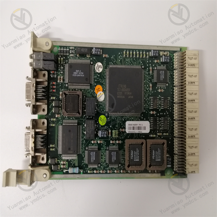
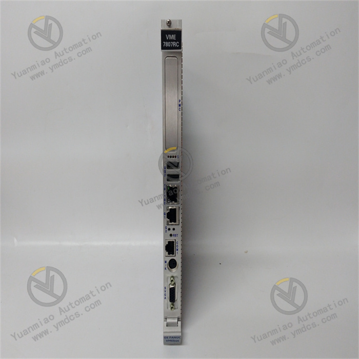
GE IS200TVIBH2B
I. Overview
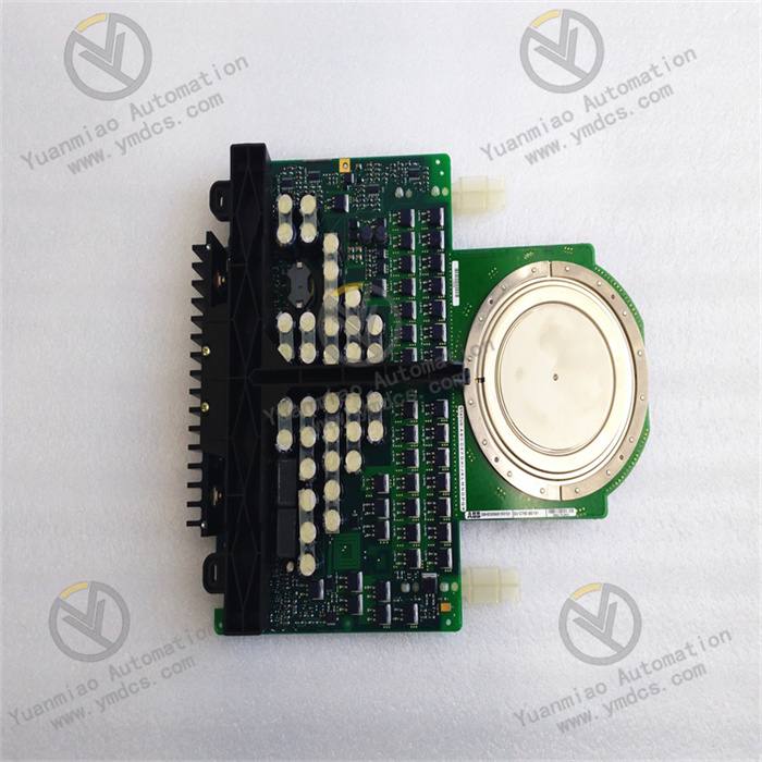
The GE IS200TVIBH2B is a high-performance vibration input module, belonging to the core component family of the GE Mark VIe series steam turbine generator control system. Its core positioning is the "vibration signal acquisition and preprocessing center" for key rotating equipment such as steam turbine generators in thermal power plants and nuclear power plants, as well as large compressors. Integrating decades of GE's technical accumulation in the fields of industrial control and rotating machinery monitoring, this module adopts a high-precision signal conditioning architecture, multi-channel synchronous acquisition design, and anti-interference reinforcement scheme. It undertakes key tasks such as real-time acquisition of critical parameters (e.g., shaft vibration, bearing vibration, and rotational speed) of rotating machinery, signal filtering, range conversion, and high-speed data interaction with the control system. Meanwhile, it features deep compatibility with GE Mark VIe controllers, HMI (Human-Machine Interface), and vibration analysis software, ensuring high-precision and low-latency transmission of vibration monitoring data from acquisition to upload.
II. Technical Parameters
| Parameter Category | Specific Specifications | Detailed Description |
|---|---|---|
| Core Acquisition & Conditioning Parameters | Channel Configuration | 4 independent vibration input channels + 2 rotational speed/keyphasor input channels; supports synchronous acquisition between channels with synchronization accuracy ≤ 100ns; each channel has an independent signal conditioning unit supporting separate parameter configuration |
| Input Signal Type | Vibration input: Eddy current displacement sensor (-24V power supply, input range ±20Vpp), piezoelectric acceleration sensor (4-20mA current signal or ±5Vpp voltage signal); Rotational speed/keyphasor input: Magnetoelectric speed sensor (0.1-10Vpp), photoelectric speed sensor (5-24VDC pulse) | |
| Acquisition Accuracy & Resolution | Voltage signal accuracy: ±0.05% FS; Current signal accuracy: ±0.1% FS; Rotational speed measurement accuracy: ±0.01rpm; Sampling resolution: 16-bit; Sampling rate: Adjustable 1kS/s-100kS/s (single channel), 1kS/s-25kS/s (4-channel synchronization) | |
| Signal Conditioning Capability | Supports hardware filtering: Low-pass filtering (adjustable cutoff frequency 10Hz-10kHz), high-pass filtering (adjustable cutoff frequency 0.1Hz-1kHz); Supports gain adjustment: 4 levels (1x, 2x, 5x, 10x); Equipped with signal linearization and zero calibration functions | |
| Measurement Range | Displacement measurement range: 0-50mm (for eddy current sensors); Acceleration range: 0-500m/s² (for piezoelectric sensors); Rotational speed measurement range: 1-10000rpm; Keyphasor phase measurement range: 0-360° with accuracy ±0.1° | |
| Communication & Interface Parameters | Communication Interface | Standard ControlNet industrial bus interface, 1 EtherNet/IP interface; Supports direct connection to the backplane bus of GE Mark VIe controller; Equipped with debugging interface (RS232) for parameter configuration and fault diagnosis |
| Communication Performance | ControlNet transmission rate: 5Mbps, communication latency ≤1ms; EtherNet/IP transmission rate: 100Mbps (full-duplex), data update cycle ≤5ms; Supports master-slave communication mode for multi-module collaborative acquisition | |
| Terminal Interface | Signal access via IS200TBCIH1B terminal board; Terminal type: Plug-in Phoenix terminal; Supported wire specification: 0.5-2.5mm²; Features anti-misplug and anti-drop design, supporting hot swapping (signal side) | |
| Anti-Interference & Reliability Parameters | Anti-Interference Performance | Complies with IEC 61000-4 standard: ESD contact discharge ±8kV, air discharge ±15kV; Surge immunity ±2kV (line-to-ground); EFT/B immunity ±1kV (5kHz/50kHz); Electromagnetic radiation complies with EN 55032 Class B standard |
| Reliability Indicators | MTBF (Mean Time Between Failures): ≥1,000,000 hours; Supports channel fault self-diagnosis and isolation; Equipped with redundant power input interface supporting hot backup switching | |
| Power Supply & Environmental Parameters | Power Supply Parameters | Input power supply: 24VDC (wide-range adaptation 18-32VDC); Power consumption: ≤12W (full-load operation); Equipped with overvoltage, overcurrent, reverse connection, and surge protection functions; Supports dual-power redundant input |
| Environmental Parameters | Operating temperature: 0℃-60℃; Storage temperature: -40℃-85℃; Relative humidity: 5%-95% (non-condensing); Vibration resistance: 5g (10-500Hz); Shock resistance: 20g (peak, 11ms); Protection class: IP20 (module body) | |
| Physical & Installation Parameters | Dimensional Specifications | 160mm×100mm×60mm (length×width×height); Compatible with standard cabinet slots of GE Mark VIe series (3U height) |
| Installation Method | Plug-in installation in cabinet slot (with anti-loose latch); Connected to system bus via backplane connector; Equipped with status indicators on the front panel for intuitive display of power supply, communication, and channel status |
III. Functional Features
1. High-Precision Multi-Channel Synchronous Acquisition for Accurate and Efficient Data Collection
2. Flexible Signal Conditioning for Compatibility with Multiple Sensor Types and Scenarios
3. High-Speed Bus Communication for Seamless Integration with Control Systems
4. Strong Anti-Interference and Redundancy Design for Stable and Reliable Operation
5. Convenient Debugging and Maintenance for Reduced Operating Costs
6. Deep Compatibility with GE Ecosystem for Flexible System Expansion
IV. Common Faults and Solutions
| Fault Phenomenon | Possible Causes | Solutions | Precautions |
|---|---|---|---|
| Module fails to start, power indicator is off | 1. 24VDC power supply not connected or loose backplane connection; 2. Power supply voltage out of the 18-32VDC range; 3. Backup power failure in dual-power redundant configuration; 4. Damaged internal power module; 5. Poor contact of cabinet slot | 1. Check power wiring and backplane connector, re-plug and fasten; 2. Measure power supply voltage with a multimeter to ensure it is within the adaptive range; 3. Switch to single-power supply to troubleshoot backup power failure; 4. Replace the internal power module of the module; 5. Pull out the module to clean the gold fingers, reinsert and lock the latch | The main power supply must be disconnected before operation to avoid electric shock; GE original accessories must be used for replacing the power module |
| Abnormal vibration data of a certain channel (no display/large fluctuation/large deviation) | 1. Loose sensor wiring or poor terminal contact; 2. Damaged or uncalibrated sensor; 3. Incorrect configuration of channel filter or gain parameters; 4. Faulty channel signal conditioning circuit; 5. Loose sensor installation or position deviation | 1. Check the wiring between the sensor and the terminal board, re-fasten; 2. Replace with a calibrated sensor for testing; 3. Verify and correct channel parameters via Proficy software; 4. Replace the module or repair the signal conditioning circuit; 5. Re-fix the sensor and check the installation position and gap | Calibration must use equipment traceable to national metrological standards; the sensor installation gap must comply with the manufacturer's specifications (e.g., the gap of eddy current sensors is usually 2mm) |
| No data or inaccurate measurement of rotational speed/keyphasor channel | 1. Incorrect or loose wiring of the speed sensor; 2. Excessive gap (>1.5mm) between the magnetoelectric sensor and the speed measuring gear; 3. Damaged sensor; 4. Incorrect configuration of rotational speed range or signal type; 5. Severely worn or oily speed measuring gear | 1. Check the sensor wiring and reconnect according to polarity; 2. Adjust the gap between the sensor and the gear to 0.5-1mm; 3. Replace the speed sensor; 4. Enter the software to configure the rotational speed signal type and range; 5. Clean or replace the speed measuring gear | The equipment must be shut down when adjusting the sensor gap; anhydrous ethanol must be used to clean the speed measuring gear to avoid residual oil affecting measurement |
| Communication fault, unable to connect to the controller | 1. Loose or damaged bus cable; 2. Incorrect configuration of communication parameters (address, baud rate, protocol); 3. Damaged bus interface; 4. Faulty controller communication port; 5. Excessively high bus load rate (>70%) | 1. Replace the bus cable and re-fasten the connector; 2. Verify that the communication parameters of the module and the controller are consistent; 3. Replace the module's bus interface or the entire module; 4. Check the controller's communication port and restart the controller; 5. Reduce the number of bus nodes or optimize the data update cycle | The module and controller must be restarted for modified communication parameters to take effect; it is recommended to monitor the ControlNet bus load rate with a dedicated tool |
| Asynchronous multi-channel data or excessive delay | 1. Incorrect configuration of synchronous acquisition parameters; 2. Excessively high sampling rate causing data congestion; 3. Excessive bus communication delay; 4. Asynchronous clocks between the module and the controller; 5. Data transmission blocked by channel fault | 1. Enter the software to reconfigure synchronous acquisition parameters and enable channel synchronization function; 2. Reduce the sampling rate to a reasonable range (e.g., 10kS/s); 3. Check bus connections and reduce bus load; 4. Synchronize the clocks of the module and the controller via software; 5. Troubleshoot and isolate the faulty channel | The configuration of synchronization parameters must be performed by professional engineers; the adjustment of sampling rate must balance monitoring accuracy and system performance |