Description
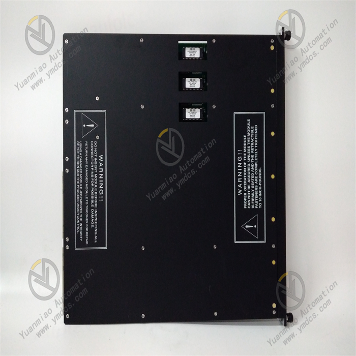
GE IS200WNPSH1ABA
The GE IS200WNPSH1ABA is a network communication module belonging to the Mark VIe turbine control system. Its core positioning is a "high-speed data interaction unit between the turbine control network and external systems". Its core value lies in integrating GE's patented redundant communication technology and multi-protocol compatibility, providing an integrated solution of "high-reliability redundant communication + multi-protocol conversion + secure data transmission" for the control networks of gas turbines and steam turbines.
Compared with general industrial communication modules, it focuses more on "turbine scenario communication requirements" — it supports bidirectional data interaction between GE's dedicated industrial Ethernet (Ethernet I/O Bus) and general Ethernet (Ethernet/IP, Modbus TCP), holds SIL 2 safety certification (IEC 61508), and has the ability to withstand high vibration (≤5g) and high temperature (ambient temperature ≤65℃). It can operate stably under the harsh working conditions of high electromagnetic interference and high data throughput in turbines. By collaborating with the Mark VIe controller and I/O modules, it realizes bidirectional transmission of turbines, including "upload of turbine control data (to DCS/cloud platform) + download of command data (to I/O modules)". In case of network failure, the redundant link can switch seamlessly within ≤50ms, avoiding equipment shutdown caused by interrupted turbine control data. It is a key communication component for "networked control and remote monitoring" of turbine equipment in industries such as power generation, petrochemicals, and aerospace.
As a core network node of the Mark VIe control system, this module supports seamless integration with the GE Predix cloud platform, third-party DCS (e.g., Siemens PCS 7, ABB AC 800M), and local HMI. It balances the real-time performance of turbine control and the flexibility of system integration, providing stable data transmission support for "remote operation and maintenance" and "predictive maintenance" of turbine equipment.
- Redundant Communication Guarantee: Both the internal Ethernet I/O Bus and external Ethernet support dual-link redundancy. When the main link is interrupted due to electromagnetic interference or physical failure, the backup link switches within ≤50ms, ensuring uninterrupted turbine control data (e.g., speed commands, interlock signals) and meeting the turbine safety requirement of "no single point of communication failure".
- High-Real-Time Transmission: Internal communication latency is ≤1ms (between Mark VIe controller and I/O modules), meeting the high-speed control requirements of turbines (e.g., rotor speed adjustment response time ≤10ms); external communication latency is ≤10ms (with DCS), ensuring real-time upload of turbine operating data (e.g., temperature, pressure) to the monitoring system.
- Optimization of Turbine-Specific Protocols: The GE-dedicated Ethernet I/O Bus protocol is optimized for the characteristics of turbine control data, adopting a "priority scheduling" mechanism (control commands have higher priority than ordinary monitoring data) to avoid control command delays under high data throughput (e.g., during turbine startup).
- Full-Scenario Protocol Coverage: Supports Ethernet/IP (adapting to Rockwell DCS), Modbus TCP (adapting to Siemens/ABB DCS), OPC UA (adapting to GE Predix cloud platform), and Modbus RTU (adapting to local instruments). It can connect to systems from different manufacturers without additional protocol converters, reducing the integration cost of turbine control systems.
- Bidirectional Data Interaction: Enables "upload of turbine control data" (e.g., temperature, pressure, speed uploaded to DCS/cloud platform) and "download of external commands" (e.g., load adjustment commands issued by DCS, parameter configuration commands issued by cloud platform), and supports data filtering and forwarding (only transmitting key data to reduce bandwidth usage).
- Secure Data Transmission: The OPC UA protocol supports SSL/TLS encryption to prevent turbine operating data (e.g., fuel flow, vibration values) from being stolen or tampered with during transmission; supports IP address filtering (only allowing authorized IP access) to prevent unauthorized devices from accessing the control network.
- High Vibration and High-Temperature Resistance: The 5g vibration resistance design adapts to mechanical vibration caused by high-speed rotation of turbine rotors; the 0℃-65℃ operating temperature range covers high temperatures in turbine rooms in summer (≤60℃ without air conditioning); communication chips adopt wide-temperature packaging (-40℃-85℃), ensuring no packet loss or disconnection in extreme working conditions.
- Resistance to Strong Electromagnetic Interference: Strong electromagnetic radiation generated by turbine generators and inverters can interfere with network signals. The module adopts a three-layer EMC design of "shielded RJ45 interfaces + signal filtering + grounding isolation", resulting in an Ethernet communication bit error rate ≤10⁻⁹ (far lower than the industrial requirement of 10⁻⁶), and the RS-485 communication anti-interference capability complies with the EN 50082-2 standard.
- Dual Power Redundancy and Overvoltage Protection: Supports dual 24V DC power redundancy (switching time ≤10ms) to avoid communication interruption caused by single power failure; communication terminals have overvoltage protection (≤60V DC) to prevent damage to module communication interfaces due to leakage of external equipment.
- Visual Configuration and Debugging: IP addresses, protocol parameters, and data transmission rules (e.g., "only upload over-temperature alarm data") can be configured graphically via GE ToolboxST software. It supports online monitoring of communication status (rate, packet loss rate) of each interface, allowing non-professional network engineers to complete basic configuration within 30 minutes.
- Remote Network Management: Supports the SNMPv3 protocol, enabling operation and maintenance personnel to remotely monitor the module's operating status (e.g., link status, power voltage) via network management software (e.g., GE CIMPLICITY). When a link failure occurs, alarm information (e.g., email, SMS) is automatically sent to shorten fault diagnosis time.
- Fault Self-Diagnosis and Localization: Automatically detects link failures (displays "Link Down"), IP address conflicts (displays "IP Conflict"), and protocol anomalies (displays "Protocol Error"). Fault information is clearly displayed via LED indicators and HMI, allowing operation and maintenance personnel to quickly locate problem points (e.g., replacing faulty network cables, adjusting IP addresses).
The Mark VIe control system of a 300MW gas turbine generator set needs to communicate with the plant's Siemens PCS 7 DCS and GE Predix cloud platform: 1. Upload real-time operating data (e.g., rotor temperature, fuel flow, power generation, update frequency 1s) to the DCS; 2. Upload historical data (e.g., average speed and vibration values every 5 minutes for predictive maintenance) to the cloud platform; 3. Receive load adjustment commands issued by the DCS (e.g., increasing from 200MW to 250MW). Requirements include communication redundancy, no data loss, and the environment is the plant control room (temperature 20℃-30℃, no dust, with electromagnetic interference).
- Multi-Protocol Communication Configuration: Configure the external Ethernet 1 interface with the Modbus TCP protocol (for communication with the PCS 7 DCS), the external Ethernet 2 interface with the OPC UA protocol (for communication with the Predix cloud platform), and the RS-485 interface with the Modbus RTU protocol (for communication with local vibration instruments).
- Redundancy and Data Interaction: Adopt dual-link redundancy for the external Ethernet (switch to the backup link within ≤50ms in case of main link failure), upload 16 channels of key data to the DCS (update frequency 1s), 8 channels of historical data to the cloud platform (update frequency 5 minutes), and receive 2 channels of control commands (load adjustment, emergency shutdown) issued by the DCS.
- Data Security and Monitoring: Enable SSL/TLS encryption for OPC UA communication; IP address filtering only allows access from authorized IPs of the DCS and cloud platform; monitor communication status via ToolboxST software, and trigger an HMI alarm when the packet loss rate exceeds 0.1% to prompt operation and maintenance personnel to troubleshoot link issues in a timely manner.
A 6MW steam turbine (driving a catalytic fan) in a petrochemical catalytic cracking unit needs to realize: 1. Local HMI monitoring (displaying steam pressure, speed, valve status, update frequency 0.5s); 2. Remote DCS (ABB AC 800M) monitoring (uploading operating data, receiving load adjustment commands); 3. Data collection from local instruments (e.g., pressure transmitters, temperature transmitters). The environment is the catalytic workshop (high dust, strong electromagnetic interference, temperature 25℃-40℃).
- Multi-Interface Collaborative Communication: The internal Ethernet I/O Bus interface communicates with the Mark VIe controller (latency ≤1ms); the external Ethernet 1 interface communicates with the local HMI (Ethernet/IP protocol, update frequency 0.5s); the external Ethernet 2 interface communicates with the ABB AC 800M DCS (Modbus TCP protocol); the RS-485 interface collects data from 3 local pressure transmitters (Modbus RTU protocol).
- Anti-Interference and Dust Protection: Use shielded twisted-pair cables for Ethernet (single-end grounding of the shield layer); install the module in a sealed control cabinet (IP54) to prevent dust from entering the communication interfaces; use differential signals for RS-485 communication to resist electromagnetic interference generated by inverters in the catalytic workshop.
- Data Filtering and Forwarding: Only upload 8 channels of key data (steam pressure, speed, current) to the DCS, and send all operating data to the local HMI to reduce bandwidth usage (Ethernet bandwidth utilization ≤30%).
A small turbine in an aero-engine ground test bench needs to transmit real-time test data (e.g., combustion chamber temperature, rotor speed, fuel pressure, update frequency 100ms) to a remote monitoring center (1km away from the test bench) and receive test commands issued by the monitoring center (e.g., startup, shutdown, fuel flow adjustment). Requirements include communication latency ≤50ms, no packet loss, and the environment is the test bench workshop (high shock, startup/shutdown shock ≤30g, temperature -10℃-60℃).
- High-Speed and Low-Latency Communication: Use the external Ethernet in 100Mbps full-duplex mode (for communication with the remote monitoring center), with a data update frequency of 100ms and communication latency ≤30ms (meeting test requirements); enable the data buffer (128KB) to avoid data loss during high shock of the test bench.
- High-Shock Adaptation and Redundancy: Fix internal components of the module with anti-vibration glue; use locked RJ45 for Ethernet interfaces (to prevent network cable detachment due to shock); adopt dual-link redundancy for the external Ethernet (switch within ≤50ms in case of main link failure) to ensure continuous transmission of test data.
- Remote Commands and Monitoring: The monitoring center issues test commands (e.g., "adjust fuel flow to 50L/h") via the Modbus TCP protocol, and the module forwards them to the Mark VIe controller; real-time test data is uploaded to the monitoring center for generating test reports and analyzing turbine performance.
![]()