Description
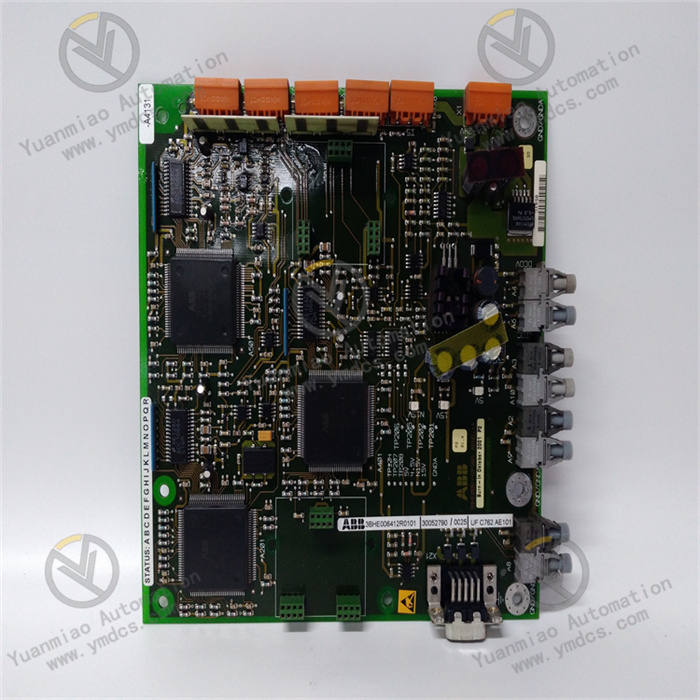
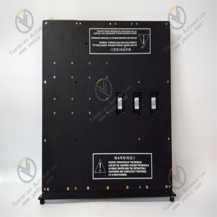
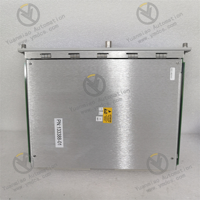
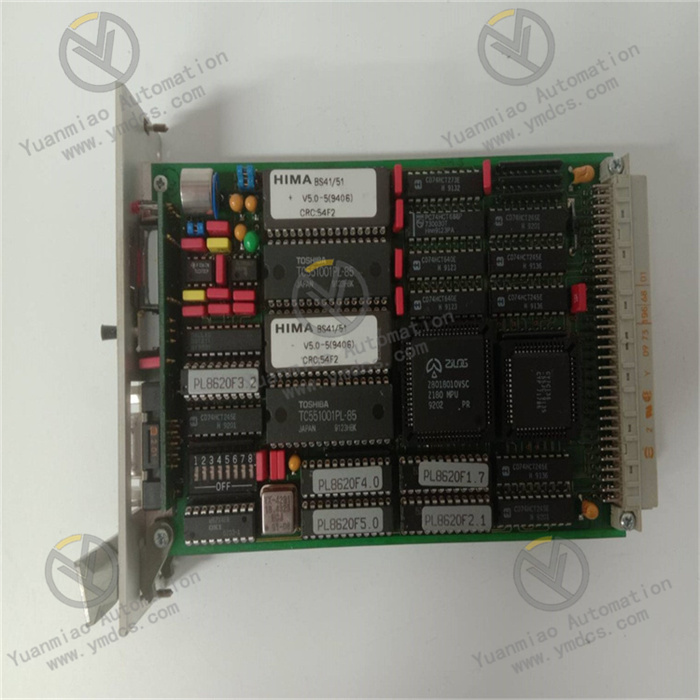
GE IS230TVBAH2A
I. Overview
II. Functional Features
- High-precision multi-parameter control: Supports closed-loop control of multiple steam turbine parameters, including speed, load, main steam pressure, and reheat steam temperature. The speed control accuracy reaches ±0.01% of the rated speed, and the load control response time is ≤100ms. It can accurately meet the full-operating-condition control requirements of steam turbines (from startup, speed-up, grid connection to full-load operation), effectively improving the unit's operating efficiency.
Full-operating-condition adaptive control: Built-in full-operating-condition control logics (e.g., startup control, speed-up control, grid connection control, load regulation, and shutdown control) and has the ability to automatically judge the unit's operating status and switch control modes. For complex scenarios such as variable load and variable operating conditions, an adaptive PID algorithm is adopted to optimize control parameters in real time, ensuring the stable operation of the unit.
- Comprehensive safety protection mechanism: Integrates multiple safety interlock functions, including overspeed protection, overpressure protection, excessive vibration protection, and high oil temperature protection. When parameters exceed the safety threshold, it can trigger protection actions (e.g., emergency shutdown, load reduction) within 50ms, while recording the parameter curve at the moment of the fault to provide a basis for fault analysis. It complies with the IEC 61508 functional safety standard and achieves a Safety Integrity Level (SIL) of 2.
Powerful communication and integration capability: Equipped with dual-redundant EtherNet/IP communication interfaces and an RS485 backup communication interface, supporting mainstream industrial communication protocols such as PROFINET and Modbus TCP. It can seamlessly connect with the Mark VIe control system master station, DCS system, HMI (Human-Machine Interface), and equipment management platform to realize control command issuance, real-time data upload, and remote monitoring functions. It supports distributed control networking of up to 32 devices.
- Industrial-grade high-reliability design: Adopts military-grade processors and components, and supports hot-swapping. The Mean Time Between Failures (MTBF) exceeds 150,000 hours. The module uses a sealed, dust-proof, and corrosion-resistant housing with an IP54 protection rating, enabling stable operation in industrial scenarios with a wide temperature range of -40℃~70℃ and a humidity range of 0~95% (non-condensing). It has strong anti-electromagnetic interference capability and is certified to the EN 61000-6-2 industrial electromagnetic compatibility standard.
Convenient debugging and operation & maintenance: Supports control logic programming, parameter configuration, fault diagnosis, and firmware upgrade via the GE Proficy Machine Edition debugging software. Equipped with a high-definition LCD display panel and buttons, it allows intuitive viewing of real-time control parameters, operating status, and fault codes, as well as on-site manual operation and parameter adjustment. The built-in parameter backup and restoration function simplifies the debugging process of batch equipment.
- Fault self-diagnosis and early warning: Features dual-level self-diagnosis (module-level and channel-level), which can real-time monitor key links such as power supply status, communication links, input/output channels, and sensor signals. When issues such as sensor drift, channel failure, or communication interruption occur, it immediately sends alarm signals via indicator lights, the LCD panel, and communication interfaces, and generates fault logs containing fault type, occurrence time, and associated parameters, facilitating maintenance personnel to quickly locate problems.
III. Technical Parameters
| Parameter Category | Parameter Name | Specific Parameters | Unit |
|---|---|---|---|
| Basic Parameters | Model | GE IS230TVBAH2A | - |
| Overall Dimension (L×W×H) | 320×180×150 | mm | |
| Weight | 5.8 | kg | |
| Installation Method | 19-inch standard rack-mounted installation | - | |
| Power Supply Parameters | Operating Voltage | 24VDC (±10%) | V |
| Rated Operating Current | 12 | A | |
| Power Consumption | ≤288 | W | |
| Control Performance Parameters | Speed Control Range | 0-3600 | r/min |
| Speed Control Accuracy | ±0.01% of rated speed | - | |
| Load Control Range | 0-100% of rated load | - | |
| Control Response Time | ≤100 | ms | |
| Input/Output Parameters | Analog Input (AI) | 16 channels, switchable between 0-10V/4-20mA, 16-bit resolution | channel |
| Analog Output (AO) | 8 channels, switchable between 0-10V/4-20mA, 16-bit resolution | channel | |
| Digital Input (DI) | 32 channels, switchable between PNP/NPN, response time ≤10μs | channel | |
| Digital Output (DO) | 16 channels, relay output, contact rating 2A/250VAC | channel | |
| Communication & Environmental Parameters | Communication Interface | 2×EtherNet/IP (1Gbps, redundant), 1×RS485 | - |
| Operating Temperature | -40~70 | ℃ | |
| Protection Rating | IP54 | - |
IV. Working Principle
Based on a closed-loop control architecture of "signal acquisition - logical operation - control output - status feedback" and combined with professional control logics for steam turbine operation, the GE IS230TVBAH2A realizes precise control of steam turbines under full operating conditions. The specific working principle is as follows:
- Operating Parameter Acquisition Stage:The module accesses various sensor signals of the steam turbine through 16 analog input channels, including speed signals collected by speed sensors (e.g., magnetoresistive sensors), main steam pressure/reheat steam pressure signals collected by pressure transmitters, bearing temperature/cylinder temperature signals collected by thermocouples, and load signals collected by load sensors. The analog input circuit performs filtering, isolation, amplification, and A/D conversion on the signals, converting analog signals into 16-bit digital signals to ensure signal accuracy and stability.
The 32 digital input channels receive the status signals of the steam turbine, such as valve limit signals, oil pump operating status signals, interlock protection trigger signals, and manual/automatic switching signals. The digital input circuit adopts an optoelectronic isolation design to effectively avoid electromagnetic interference in industrial sites and ensure reliable transmission of status signals.
Core Logical Operation Stage:The converted digital signals are transmitted to the module's multi-core processor (the main processor adopts a GE-customized PowerPC architecture). The processor calls preset control logic programs (e.g., startup speed-up curve, load regulation algorithm, safety interlock logic) and combines control parameters configured via the debugging software (e.g., PID parameters, safety thresholds, operating condition switching conditions) to perform comprehensive calculations on the real-time collected parameters.
For different operating conditions, the processor automatically switches control strategies: During the startup phase, it controls the steam turbine speed to gradually increase to the rated speed according to the preset speed-up curve; during the grid connection phase, it achieves synchronization with the grid frequency through fine speed adjustment to complete the grid connection operation; during the full-load operation phase, it adjusts the opening of the steam inlet valve using an adaptive PID algorithm based on grid load demand and changes in steam parameters to realize precise load control; under abnormal operating conditions, the processor quickly identifies the fault type and triggers the corresponding safety protection logic.
Control Output and Execution Stage:Based on the calculation results, the processor outputs control signals through 8 analog output channels, such as 4-20mA signals for adjusting the opening of the steam inlet valve and 0-10V signals for controlling the oil pump pressure. The analog output circuit performs D/A conversion and power amplification on the signals to ensure that the output signals can stably drive the action of actuators (e.g., servo valves, control valves).
The 16 digital output channels output switching value control commands, such as controlling the start/stop of oil pumps, the on/off of solenoid valves, and the on/off of fault alarm lights. The relay output circuit realizes isolation between strong current and weak current, ensuring the safety of the module's internal circuit and the reliable action of actuators.
- Communication and Status Feedback Stage:The module transmits the real-time operating parameters (speed, load, pressure, temperature) of the steam turbine, the execution status of control commands, and fault information to the Mark VIe main controller, DCS system, and HMI via dual-redundant EtherNet/IP communication interfaces, while receiving control commands (e.g., load setpoint, startup/shutdown commands) and parameter adjustment commands issued by the upper-level system.
- The LCD display panel refreshes and displays key operating parameters, the current operating condition mode, and fault codes in real time. Buttons enable on-site manual intervention (e.g., manual load adjustment, fault reset); when a fault is detected, the module immediately triggers an audible and visual alarm, sends an alarm signal to the upper-level system via the communication interface, and triggers emergency shutdown protection if necessary to ensure the safety of the unit.
V. Common Faults and Troubleshooting Methods
| Fault Phenomenon | Possible Causes | Troubleshooting Methods | Precautions |
|---|---|---|---|
| No display when the module is powered on, and the power indicator light is off | 1. Input power not connected or abnormal voltage; 2. Loose or oxidized power terminals; 3. Damaged internal power module of the module; 4. Burned internal fuse (3A fuse) | 1. Use a multimeter to detect the input power voltage and ensure it is 24VDC±10%; 2. After power-off, re-tighten the power terminals and clean the oxide layer with fine sandpaper; 3. Contact GE official after-sales to replace the original power module; 4. Remove the module front panel, replace the fuse with the same specification (3A/250V), and check the cause of short circuit before replacement | GE original spare parts must be used for replacing the power module and fuse; third-party products are prohibited. The main power must be cut off and an anti-static wristband must be worn before operation. |
| Decreased speed control accuracy with excessive fluctuation (Fault code: ERR-SPD-01) | 1. Loose speed sensor or deviated installation position; 2. Severe sensor signal interference; 3. Drifted PID control parameters; 4. Aging or damaged speed sensor | 1. After shutdown, check the tightness of the sensor installation and re-calibrate the installation position (0.5-1mm gap with the gear); 2. Replace the sensor cable with a shielded twisted pair and ground the shield layer at a single point; 3. Re-optimize the PID parameters via the debugging software or restore the default parameter configuration; 4. Use an oscilloscope to detect the sensor output signal, and replace the sensor with the same model if abnormal | Professional tools must be used for sensor calibration to ensure the installation gap meets requirements. PID parameter optimization should be carried out when the unit is under no-load, with gradual adjustment and testing. |
| No signal from the analog input channel (Fault code: ERR-AI-03) | 1. Loose or broken wiring between the sensor and the module; 2. Sensor not powered on or damaged; 3. Incorrect channel jumper setting (wrong switching between 4-20mA/0-10V); 4. Damaged input channel circuit | 1. After power-off, check the terminals, re-plug and tighten the wiring; 2. Detect the sensor power supply, use a multimeter to measure the sensor output signal to confirm if it is normal; 3. Check the process requirements and adjust the hardware jumper of the corresponding channel to the correct position; 4. Contact GE after-sales to detect the channel circuit and replace the input module if necessary | Wiring operations must be carried out when the unit is shut down. Anti-static equipment must be worn in the semiconductor workshop. Channel calibration must be re-performed after replacing the module. |
| Communication interruption, unable to connect to the upper-level system (Fault code: ERR-COM-02) | 1. Loose, damaged, or incorrectly wired communication cable; 2. Mismatched communication parameters (IP address, port number, protocol); 3. Faulty communication interface of the upper-level system; 4. Damaged communication module of the module | 1. Check the EtherNet/IP cable, re-plug and tighten it, replace the damaged cable, and verify the A/B line wiring; 2. Check the communication parameters between the module and the upper-level system via the debugging software, ensure they are consistent, and restart the module; 3. Connect the cable to the backup communication interface to verify if the upper-level system interface is normal; 4. Contact after-sales to replace the communication module | The module must be restarted for the modified communication parameters to take effect. Redundant communication links are recommended in industrial sites to improve reliability. Industrial-grade shielded cables must be used for communication cables. |
| No action of the actuator with abnormal analog output (Fault code: ERR-AO-01) | 1. Loose or broken wiring between the output channel and the actuator; 2. Faulty actuator or load exceeding the rated range; 3. Uncalibrated output channel or lost calibration data; 4. Damaged output drive circuit of the output channel | 1. After power-off, check the wiring and re-tighten it; 2. Detect the actuator impedance to ensure it is within the rated load range, and test if the actuator operates when powered separately; 3. Re-calibrate the output channel via the debugging software and import the backed-up calibration data; 4. Contact after-sales to replace the output drive module | A standard signal source must be used for channel calibration, and no-load testing must be performed after calibration. Actuator faults may cause module overload, so actuator issues should be prioritized for troubleshooting. |
| Unable to start the unit, reporting "interlock protection triggered" fault (Fault code: ERR-INT-05) | 1. Key safety parameters exceeding the threshold (e.g., high oil temperature, low oil pressure); 2. Abnormal interlock input signal (DI channel fault); 3. Mis-modified interlock logic program; 4. Unreset manual interlock button | 1. Check safety parameters such as oil temperature, oil pressure, and vibration, identify and handle the cause of parameter abnormality; 2. Use a multimeter to detect the interlock input DI channel signal and repair the faulty channel; 3. Compare with the backed-up program via the debugging software and restore the correct interlock logic; 4. Check the on-site manual interlock button and reset it to the normal state | Forced startup of the unit is prohibited when interlock protection is triggered; the cause of the fault must be thoroughly identified. The original program must be backed up before modifying the control logic program, and the operation must be performed by professional engineers. |