Description
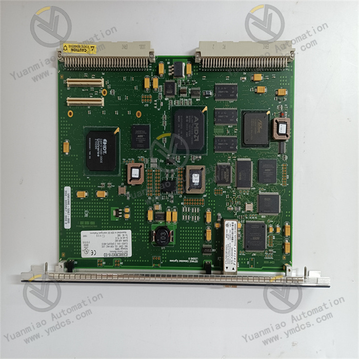
GE IS230SNCIH6A
The GE IS230SNCIH6A is a high-performance industrial-grade digital input module, which belongs to the core I/O component matrix of GE's Mark VIe Distributed Control System (DCS) and Speedtronic turbine control system. Its core positioning is to serve as a "front-end hub" for digital signal acquisition in industrial sites, focusing on high-precision and high-reliability acquisition of various digital input signals such as equipment switch status, limit signals, and alarm contacts. Through enhanced signal conditioning circuits, flexible configuration functions, and excellent anti-interference design, it provides accurate front-end data support for condition monitoring, logical interlocking, and safety protection of key industrial equipment such as turbines, boilers, and generators.
The application scenarios of this module extensively cover fields with strict requirements for real-time performance, stability, and anti-interference of digital signal acquisition, including:
- Power Energy: Acquisition of contact signals for turbine shaft vibration monitoring in thermal power units, acquisition of limit signals for boiler safety valves, and monitoring of status contacts in generator excitation systems.
- Petrochemical Industry: Acquisition of pressure switch signals for reactors in chemical plants, monitoring of limit switch status for pipeline valves, and acquisition of contact signals for pump unit operation status.
- Metallurgy and Steel: Acquisition of limit signals for roller position in rolling production lines, monitoring of status contacts for blast furnace distributors, and acquisition of tilt limit signals for steelmaking converters.
- Heavy Manufacturing: Acquisition of travel limit signals for large machine tool worktables, and monitoring of start-stop status contacts for production line conveyor chains.
As a dedicated input module for GE's high-end control systems, it can not only realize parallel and efficient acquisition of multi-channel signals but also seamlessly collaborate with system controllers, supporting rapid configuration of complex signal filtering and alarm logic. It is a key hardware foundation for building high-reliability industrial condition monitoring systems.
In terms of hardware architecture and system compatibility, the GE IS230SNCIH6A adopts a standardized modular design, which can be seamlessly integrated into the IC695 series I/O racks of the GE Mark VIe control system and Speedtronic turbine control cabinets, occupying only one standard I/O module slot. It achieves millisecond-level data interaction with the system controller through a high-speed backplane bus. The module is compatible with GE CIMPLICITY HMI and iFIX monitoring software, supporting configuration of key parameters such as channel filtering parameters, signal polarity, and alarm thresholds through a graphical interface, enabling rapid system integration without writing underlying code. Relying on its industrial-grade reinforced design, the module uses wide-temperature components, enhanced electromagnetic shielding, and anti-vibration structures, allowing stable operation in complex industrial site conditions with high temperature, high humidity, dust, strong electromagnetic interference, and high vibration, thus ensuring the continuity and accuracy of signal acquisition.
The GE IS230SNCIH6A adopts a 32-channel high-density design, enabling parallel acquisition of 32 independent digital signals within the space of one standard I/O slot. Compared with traditional 16-channel modules, its acquisition density is increased by 100%, which can significantly reduce the number of rack slots occupied, lowering system hardware costs and cabinet space requirements. The module supports flexible division of 32 channels into 4 independent groups (8 channels per group), and each group can be independently configured with input signal type (dry contact/wet contact), polarity (PNP/NPN), response time, and filtering parameters, adapting to on-site scenarios with mixed access of different types of sensors. For example, channels 1-8 can be configured as DC 24V wet contact input (connected to pressure switches), and channels 9-16 as DC 12V dry contact input (connected to limit switches), realizing centralized acquisition and differentiated management of different signal types and improving the flexibility of on-site configuration.
The module adopts a dual anti-interference mechanism of "RC hardware filtering + software digital filtering", which can effectively suppress various electromagnetic interferences in industrial sites. At the hardware level, each input channel is equipped with an independent RC filter circuit, which can filter out high-frequency interference signals above 1MHz (such as radiation interference generated by frequency converters and high-voltage motors). At the software level, it supports independent configuration of digital filtering parameters within the range of 1ms~200ms, allowing precise adjustment of filtering intensity according to signal characteristics. For instance, 1ms fast filtering can be configured for rapidly changing fault alarm signals, and 50ms strong filtering for slowly changing position limit signals, ensuring both real-time signal response and avoiding misjudgments caused by false signals. The high-strength photoelectric isolation design of 3000Vrms between channels can effectively block common-mode interference and differential-mode interference between channels; even if a short circuit fault occurs in one channel, it will not affect the normal acquisition of other channels, further enhancing the anti-interference stability of the system.
The response time of the module's input channels can be flexibly configured via software, with a minimum response time as low as 1ms, enabling accurate capture of instantaneous equipment fault signals (such as turbine shaft vibration over-limit contact signals and boiler safety valve action signals). This provides millisecond-level data support for key control logics such as system emergency shutdown and interlock protection, avoiding safety accidents caused by signal delay. The 32 channels support parallel synchronous acquisition, with an acquisition cycle as low as 1ms, enabling real-time tracking of the coordinated operation status of multiple devices (such as synchronous position monitoring of multiple sets of rollers in a rolling production line). The module conducts data interaction with the controller through a high-speed backplane bus, with a data transmission rate of ≥100Mbps; the acquired signal status can be uploaded to the controller within 1ms, ensuring the real-time and accuracy of control logic operations and meeting the monitoring needs of high-speed industrial production scenarios.
The module has a fault diagnosis coverage rate of 99.9%, integrating dual diagnosis mechanisms at the channel level and module level, enabling precise fault location and rapid troubleshooting. Channel-level diagnosis can automatically identify faults such as signal open circuit (e.g., loose sensor wiring, wire breakage), short circuit (e.g., signal wire short-circuited to ground, cross short circuit of signal wires), and abnormal signal fluctuation (e.g., frequent signal jumps caused by poor contact). Module-level diagnosis can monitor hardware issues such as abnormal power supply voltage, backplane communication failure, and isolation circuit failure. When a fault occurs, the module immediately generates a standardized fault code (e.g., E001 for channel 1 short circuit, F002 for module power fault) and issues hierarchical alarms through local LED indicators (yellow light flashes for channel faults; red light stays on for module faults). Meanwhile, it uploads fault information (faulty channel, fault type, occurrence time) to the controller and upper-level monitoring system, clearly indicating the fault location and handling suggestions (e.g., "Channel 12 is open, please check sensor wiring"), significantly shortening the operation and maintenance troubleshooting time.
The module supports 1:1 hot redundancy configuration. The main and standby modules achieve real-time data synchronization through a dedicated redundant communication link, with synchronized content including key information such as 32-channel acquisition data, configuration parameters, and fault status, and a synchronization delay of ≤1ms. During normal operation, the main module performs signal acquisition and data upload functions, while the standby module monitors the operating status of the main module in real time and synchronizes data. When the main module encounters abnormal conditions such as power failure, communication interruption, or batch channel faults, the standby module can automatically complete undisturbed switching within 15ms and take over all acquisition functions. During the switching process, no acquisition data is lost and no signal status fluctuation occurs, ensuring uninterrupted condition monitoring of key equipment such as turbines and boilers. The module has channel-level fault isolation capability; when a single channel fails, it is automatically marked as "faulty state" and shielded, without affecting the normal acquisition of the other 31 channels. Additionally, it supports remote disabling/enabling of faulty channels via software, improving the system's fault tolerance and operational stability.
The module is compatible with mainstream monitoring software such as GE CIMPLICITY HMI and iFIX, supporting full-parameter configuration through a graphical configuration interface, including channel grouping, signal type, polarity, response time, filtering parameters, and alarm thresholds. No underlying code writing is required, making the configuration process intuitive and efficient—even beginners can quickly get started. The integration and debugging cycle is shortened by more than 60% compared with traditional modules. The software has built-in rich industry application templates (such as turbine condition monitoring template and boiler safety monitoring template), which include preset channel configurations and alarm logics. After importing the template, integration can be completed by only fine-tuning parameters, further improving deployment efficiency. The module seamlessly connects with the GE Mark VIe controller through a standardized backplane bus, supporting the controller's online diagnosis, parameter modification, and firmware upgrade of the module. Maintenance operations can be completed without shutdown, reducing production interruption time. Meanwhile, it supports the Modbus TCP communication protocol, enabling flexible integration into third-party DCS systems and improving the compatibility of cross-brand system integration.
The GE IS230SNCIH6A realizes high-precision and high-reliability acquisition of digital signals through the collaboration of hardware circuits and software logic, based on the core workflow of "signal access - signal conditioning - signal acquisition - data processing - data upload - fault diagnosis". The specific working mechanism is as follows:
Digital signals from on-site sensors (such as limit switches and pressure switches) or equipment contacts are connected to the module through 32 independent input terminals and first enter the signal conditioning unit. According to the software-configured signal type (dry contact/wet contact), the conditioning unit automatically switches the power supply mode: for dry contact input, the module internally provides a stable DC 24V (or customized voltage) excitation power supply; for wet contact input, it directly collects the active signal provided by the external sensor. At the same time, the polarity switching circuit automatically adjusts the signal acquisition direction according to the configured PNP/NPN polarity to ensure correct signal polarity. The conditioned signal first passes through the RC hardware filter circuit to filter out high-frequency electromagnetic interference, and then is sent to the photoelectric isolation unit to achieve electrical isolation between the input channel and the module's internal core circuit, preventing external high-voltage and strong interference signals from invading and ensuring the safe and stable operation of the core circuit.
The signal after isolation and filtering is sent to the level detection unit, converted into a standard TTL level signal (5V for high level, 0V for low level), and then transmitted to the 32-channel parallel data acquisition unit. The data acquisition unit performs synchronous sampling of the 32-channel signals according to the configured acquisition cycle (minimum 1ms) and stores the acquired signal status (high/low level) in the temporary data register. Subsequently, the data processing unit performs software digital filtering on the signals in the temporary register, eliminating glitches and interference noise in the signals according to the filtering parameters configured for each channel to obtain stable and valid signals. At the same time, the data processing unit conducts continuity verification on the signal status; if frequent signal jumps are detected within a short period (exceeding the configured threshold), the signal is marked as "abnormal" and an alarm is triggered.
The processed valid signals are uploaded to the GE Mark VIe controller through the high-speed backplane bus at a fixed cycle (synchronized with the acquisition cycle), providing data support for the controller's logical operations and interlock control. In the redundancy configuration mode, the data processing unit of the main module synchronizes information such as 32-channel acquisition data, configuration parameters, and fault status to the redundant data register of the standby module in real time through a dedicated redundant communication link, with a synchronization frequency of 1000 times per second, ensuring complete data consistency between the main and standby modules. The redundancy monitoring unit of the standby module compares the data and operating status of the main and standby modules in real time; if abnormal data or communication interruption of the main module is detected, the redundancy switching logic is triggered immediately.
The fault diagnosis unit monitors the operating status of all components of the module in real time: channel-level diagnosis identifies faults such as open circuit, short circuit, and signal abnormality by detecting the current, voltage amplitude, and stability of the input signal; module-level diagnosis identifies hardware issues such as power fault and communication fault by monitoring the power supply voltage, backplane communication signal, and isolation circuit status. When a fault is detected, a fault code is generated immediately, triggering a local LED alarm and uploading the fault information to the upper-level system. In the redundancy configuration, when the main module fails, the redundancy switching unit of the standby module takes over the control right of the backplane bus within 15ms and uploads the processed acquisition data to the controller, realizing undisturbed switching. After the faulty main module is restored, it automatically enters the standby state, synchronizes data with the standby module through the redundant link, and waits for the next switching command. When a single channel fails, the diagnosis unit marks and shields the faulty channel, which no longer participates in data acquisition and upload, ensuring the normal operation of other channels.
![]()