Description
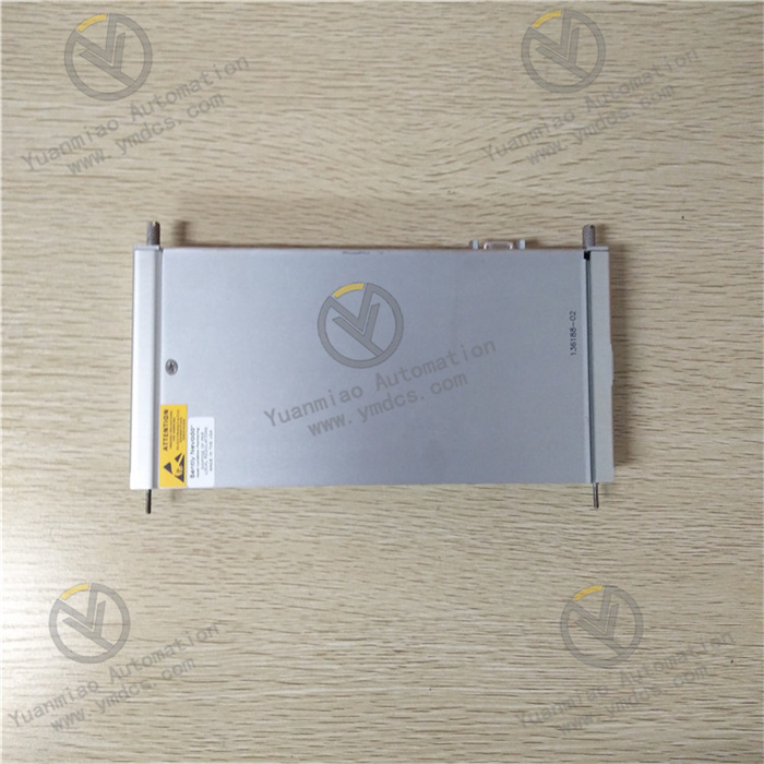
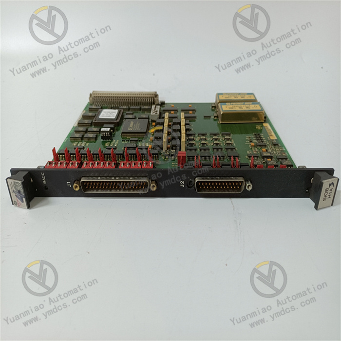
GE IS230SNRTH2A
I. Product Overview
GE IS230SNRTH2A is a high-precision speed detection module that belongs to the core signal acquisition component family of the GE Mark VIe Distributed Control System (DCS). It is specifically designed for speed monitoring and feedback scenarios of rotating mechanical equipment such as gas turbines, steam turbines, water turbines, and industrial drive motors. Its core function is to collect signals output by on-site speed sensors in real time. After undergoing signal conditioning, filtering, amplification, and digitization processing, it transmits accurate speed data to the Mark VIe controller, providing reliable data support for core control logics of equipment, such as speed closed-loop control, overspeed protection, and load distribution. Meanwhile, it is equipped with auxiliary functions like signal fault diagnosis and redundancy monitoring to ensure the safe and stable operation of rotating equipment.
II. Technical Specifications
| Parameter Category | Parameter Name | Specific Parameters | Unit |
|---|---|---|---|
| Basic Parameters | Model Number | GE IS230SNRTH2A | - |
| Product Type | High-Precision Speed Detection Module | - | |
| Series | GE Mark VIe Distributed Control System | - | |
| Compatible Rack | Mark VIe Standard I/O Rack (e.g., IC695CRU320, IC695CRU330) | - | |
| Dimension (L×W×H) | 160×100×50 | mm | |
| Installation Method | Slot Installation in Mark VIe I/O Rack (with Positioning Buckle and Anti-Misinsertion Design) | - | |
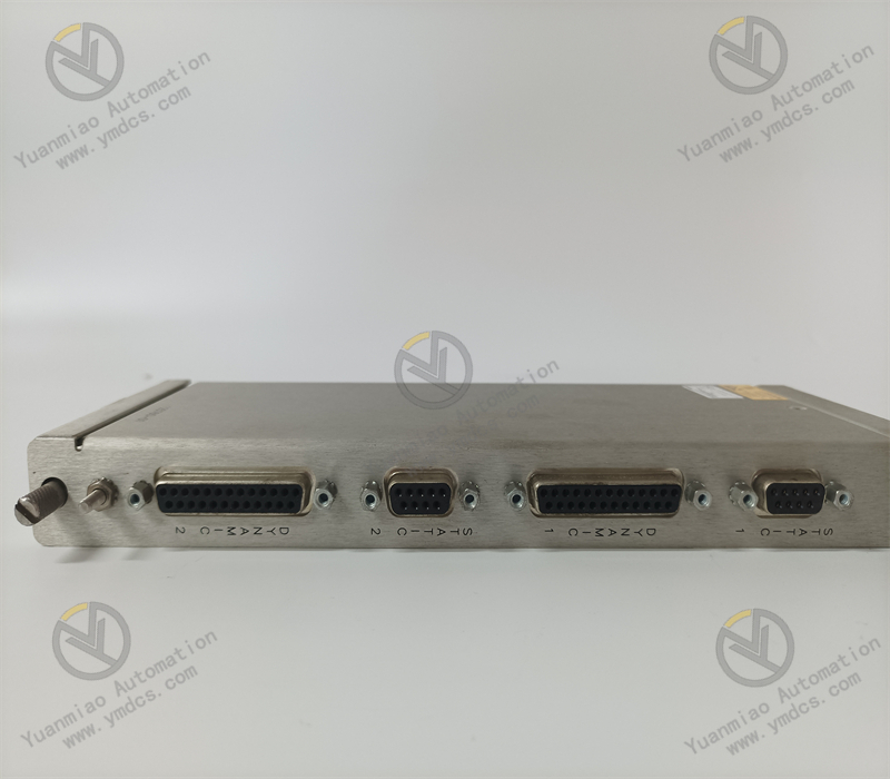
| Acquisition Performance | Number of Input Channels | 4 Independent Speed Signal Input Channels | Channel(s) |
| Parameters | Compatible Sensor Types | Magnetoelectric Speed Sensor (Variable Reluctance Type), Photoelectric Speed Sensor, Hall Effect Speed Sensor | - |
| Input Signal Range | Magnetoelectric: 0.1~10Vpp; Photoelectric/Hall Effect: 5~24VDC (Pulse Signal) | Vpp/VDC | |
| Measuring Speed Range | 1~10000 rpm (Can be extended to higher ranges via software-configured gear teeth) | rpm | |
| Measuring Accuracy | ±0.01% Full Scale (when speed ≥100 rpm); ±0.1 rpm (when speed <100 rpm) | - | |
| Response Time | ≤1ms (when speed variation ≥1% rated speed) | ms | |
| Electrical & Communication | Power Supply Voltage | DC 5V (Logic Power) + DC 24V (Sensor Power) Supplied by I/O Rack | V |
| Parameters | Maximum Power Consumption | Logic Power: ≤2.5W; Sensor Power: ≤5W (when 4 channels are fully loaded) | W |
| Isolation Performance | Inter-Channel: 1500VAC/1min; Channel-to-Backplane/Power Supply: 2500VAC/1min | VAC/min | |
| Communication Method | Communicates with Controller via Mark VIe Backplane Bus, Communication Rate: 1Gbps, Supporting Data Frame Verification | Gbps | |
| Environmental Parameters | Operating Temperature Range | -10~60℃ | ℃ |
| Storage Temperature Range | -40~85℃ | ℃ | |
| Relative Humidity | 5%~95% (No Condensation, Compliant with IEC 60068-2-3 Standard) | % | |
| EMI Resistance Performance | Compliant with IEC 61000-4-2/3/4/6 Standards, ESD ±15kV (Air)/±8kV (Contact), RF Interference Suppression ≥40dB | - |
III. Functional Features
- Deep Compatibility with Mark VIe System, Convenient and Efficient Integration: The module adopts standard hardware interfaces and communication protocols of the Mark VIe series, and can be directly inserted into any compatible slot of the Mark VIe standard I/O rack without additional adapters or custom drivers. It achieves high-speed data interaction with Mark VIe controllers (e.g., IC695CPU310, IC695CPU320) via the rack backplane bus. The 1Gbps communication rate ensures that the total delay from speed data acquisition to transmission to the controller is ≤2ms, providing accurate timing guarantee for real-time control. It supports GE Proficy Machine Edition configuration software, allowing operations such as sensor type matching, speed range setting, filter parameter configuration, and fault threshold definition to be completed via a graphical interface. It seamlessly links with the system's speed control and protection logics, enabling rapid construction of a complete speed monitoring and control system.
- Compatibility with Multiple Sensor Types, Comprehensive Scene Coverage: It integrates 4 independent speed signal input channels, and each channel can be independently configured via software to match different types, being compatible with mainstream speed sensors such as magnetoelectric, photoelectric, and Hall effect types. For magnetoelectric sensors, the module has a built-in signal conditioning circuit that can directly receive 0.1~10Vpp AC pulse signals and perform amplification and shaping. For photoelectric and Hall effect sensors, it provides an isolated DC 5~24V sensor power supply interface, supporting the acquisition of 5~24VDC DC pulse signals. This multi-type compatibility capability allows the module to be flexibly applied to different scenarios such as high-temperature shaft-end speed monitoring of gas turbines, low-speed operation feedback of motors, and blade speed measurement of water turbines, reducing the procurement cost of dedicated modules.
- High-Precision Speed Measurement, Reliable and Accurate Data: It adopts a 16-bit high-precision AD conversion chip, advanced digital frequency measurement algorithm, and adaptive filtering technology to achieve high-precision speed measurement within a wide range. Within the 100~10000 rpm range, the measurement accuracy reaches ±0.01% full scale, enabling it to accurately capture small speed fluctuations of rotating equipment. In low-speed scenarios (1~100 rpm), the period measurement method is used instead of the frequency measurement method to ensure the measurement accuracy remains at ±0.1 rpm, meeting the monitoring requirements of low-speed equipment. The module supports the configuration of parameters such as gear teeth and pulses per revolution, and can automatically convert the actual speed according to the on-site sensor installation method (e.g., number of gear teeth of the gear disc) without additional calculations by the controller, reducing the controller load.
- Comprehensive Isolation and Anti-Interference, Adaptation to Harsh Environments: It adopts a triple electrical isolation design to achieve independent isolation between input channels, between each channel and the backplane bus, and between each channel and the power supply. The isolation voltages reach 1500VAC/1min (inter-channel) and 2500VAC/1min (channel-to-backplane/power supply), effectively blocking interference from on-site ground loops, power fluctuations, and equipment electromagnetic radiation on signal acquisition. Each input channel is equipped with a hardware filtering circuit (RC filtering + digital filtering) and a surge suppression component (TVS diode), which can filter 50Hz power frequency interference and transient pulse interference, with an RF interference suppression capability of ≥40dB. Having passed the IEC 61000-4 series EMI resistance tests, it can maintain the stability and accuracy of speed data even in strong interference environments such as high-voltage motors and frequency converters.
- Hot-Swapping and Redundancy Configuration, Significantly Improved Availability: It supports the hot-swapping function, allowing the module to be directly inserted or removed for replacement or maintenance while the Mark VIe system is in operation and the controller continues to run. When the module is removed, the controller automatically identifies the channel status and marks it as "faulty," while executing the preset redundancy switching logic (e.g., switching to standby module data). After inserting a new module, the system automatically completes initialization and synchronizes configuration parameters, and can resume normal operation within 10 seconds, significantly reducing maintenance downtime. It supports dual redundancy configurations at the channel level and module level: channel-level redundancy allows the same speed signal to be connected to two different channels to achieve "dual acquisition" comparison; module-level redundancy allows the configuration of primary and standby modules, and when the primary module fails, the standby module automatically takes over data output, improving system reliability.
- Full-Dimensional Fault Diagnosis, Convenient and Efficient Operation & Maintenance: It is equipped with comprehensive online diagnosis functions, which can real-time monitor the operating status of the module's internal core components (AD converter, logic circuit, communication interface, power module), input channels (sensor open circuit, short circuit, weak/strong signal), and sensor status (abnormal power supply, signal loss). Diagnostic information includes fault type, faulty channel, fault occurrence time, and fault level, which can be viewed remotely via the diagnostic interface of the Proficy Machine Edition software or displayed intuitively on-site through the LED indicators on the front of the module (power light, operation light, channel status light, fault light). It supports the fault early warning function: when potential fault signs such as signal signal-to-noise ratio (SNR) decrease and sensor power supply voltage fluctuation are detected, early warning signals are sent in advance to assist operation and maintenance personnel in conducting predictive maintenance.
- Industrial-Grade Reinforced Design, Excellent Environmental Adaptability: It adopts industrial-grade high-reliability components and an all-metal housing design. The housing has excellent heat dissipation performance and mechanical strength, which can quickly dissipate heat generated during the module's operation, ensuring stable operation within a wide temperature range of -10~60℃. Having passed the vibration and shock tests in accordance with the MIL-STD-810G standard, it has 3g vibration resistance (5~2000Hz) and 15g shock resistance, enabling it to adapt to vibrations generated during the operation of rotating equipment and shocks during transportation and installation. The module has an IP40 protection rating, which can effectively prevent dust intrusion in industrial sites and adapt to harsh operating environments such as dusty and high-temperature power generation workshops and chemical plants.
IV. Working Principle
As the speed sensing core of the Mark VIe control system, the GE IS230SNRTH2A module realizes accurate measurement and reliable transmission of rotating equipment speed through a core workflow of "initialization & configuration loading → signal acquisition → conditioning & filtering → data calculation → transmission & feedback → fault diagnosis". The specific workflow is as follows:
- Module Initialization and Configuration Loading: After the module is installed in the Mark VIe I/O rack and powered on, it automatically starts the initialization process. First, it performs a hardware self-test, sequentially checking the integrity of the 16-bit AD converter, logic processing unit, communication interface, power module, and 4 input channels. After passing the self-test, it establishes a communication connection with the controller via the backplane bus and receives configuration parameters sent by the controller, including sensor type, gear teeth (or pulses per revolution), speed range, filter parameters, fault threshold, and redundancy configuration mode. After the initialization is completed, the module sends a "ready" signal to the controller, the LED operation light remains on, and it enters the normal working mode. If the self-test fails or the configuration parameters fail to load correctly, a fault alarm is triggered immediately, fault codes are uploaded via the communication bus, and the corresponding fault indicator is lit.
- Speed Signal Acquisition and Conditioning: On-site speed sensors (e.g., a magnetoelectric sensor installed next to the gear at the equipment shaft end) convert the mechanical speed of the rotating equipment into electrical signals (AC pulse signals for magnetoelectric type, DC pulse signals for photoelectric/Hall effect type) and transmit them to the corresponding input channels of the module. The module performs differentiated conditioning for different types of input signals: magnetoelectric signals are amplified to a standard amplitude by an isolated amplification circuit, and then high-frequency noise is filtered out by an RC filtering circuit; photoelectric/Hall effect signals directly enter the digital filtering circuit to remove power frequency interference and transient pulses. Meanwhile, the module provides isolated DC 5~24V power supply for photoelectric and Hall effect sensors to ensure stable operation of the sensors. The power supply circuit is equipped with an overcurrent protection function to prevent module damage caused by sensor short circuits.
- Speed Data Calculation and Conversion: The conditioned standard pulse signals enter the internal logic processing unit of the module. The 16-bit high-precision AD converter converts analog signals (only for magnetoelectric type) into digital signals, which are then processed by the frequency/period measurement unit for data calculation. The module automatically switches the measurement algorithm according to the configured speed range: when the speed is ≥100 rpm, the frequency measurement method is used, where the number of pulses per unit time is counted by a high-precision clock, and the actual speed is converted by combining the configured pulses per revolution parameter; when the speed is <100 rpm, it automatically switches to the period measurement method, where the pulse frequency is calculated by counting the number of clock cycles between two adjacent pulses, and then converted into the actual speed to ensure measurement accuracy in low-speed scenarios. After the calculation is completed, the data undergoes consistency verification by the verification unit to eliminate abnormal data points.
- Data Transmission and Redundancy Linkage: The speed data that has passed the verification is transmitted to the controller at a rate of 1Gbps via the Mark VIe backplane bus, providing data support for the controller's speed closed-loop control, overspeed protection, and other logics. If the module is configured in redundancy mode (channel-level or module-level), the redundancy linkage logic is executed: in channel-level redundancy, the same speed data collected by two channels is compared, and the average value is taken as the output data; if the deviation between the two sets of data exceeds the threshold, a channel fault alarm is triggered; in module-level redundancy, the primary module synchronizes speed data and working status to the standby module in real time; when the primary module fails, the standby module takes over data output within 1ms to ensure uninterrupted data transmission.
- Real-Time Diagnosis and Fault Handling: During operation, the module continuously performs full-dimensional diagnosis: ① Hardware diagnosis: periodically checks the accuracy of the AD converter, the voltage of the logic circuit, the stability of the communication link, and the output status of the power supply; ② Signal diagnosis: real-time monitors the amplitude, SNR, pulse interval consistency of the input signal, and the sensor power supply voltage; if the signal amplitude is lower than the threshold (e.g., magnetoelectric signal <0.1Vpp) or the SNR is <20dB, the signal is determined to be abnormal; ③ Redundancy diagnosis: in redundancy configuration, real-time compares the data deviation and status consistency between the primary and standby channels or primary and standby modules. When a fault is diagnosed, three actions are executed immediately: ① Upload detailed information such as fault type and faulty channel to the controller via the communication bus; ② Light up the corresponding fault indicator on the front of the module (e.g., the CH1 light flashes if channel 1 fails); ③ If redundancy is configured, automatically trigger the redundancy switching logic to ensure continuous output of speed data.