Description
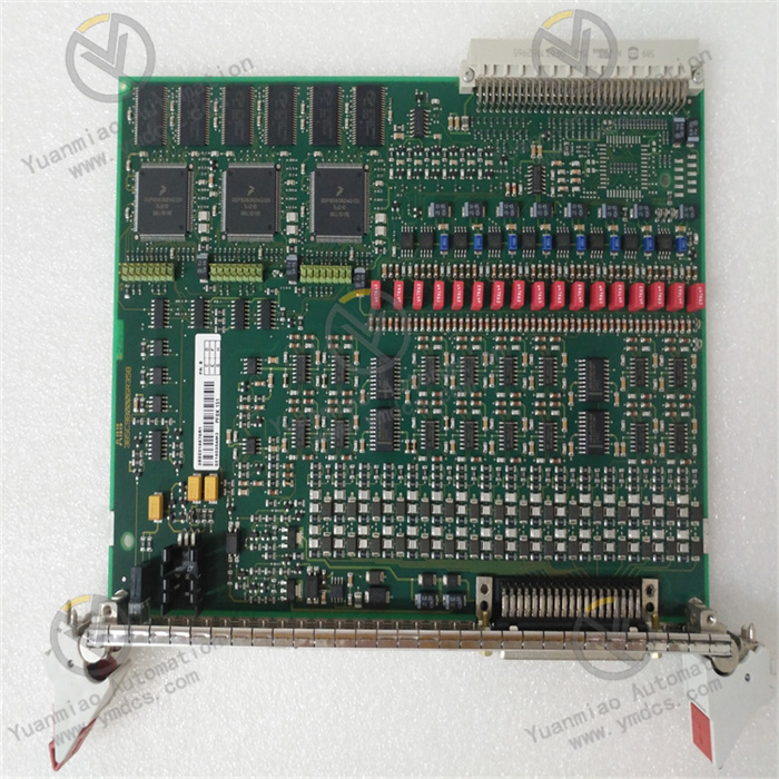
GE IS210SAMBH2AA
GE IS210SAMBH2AA is a high-precision analog input module that belongs to the core signal acquisition component family of the GE Mark VIe Distributed Control System (DCS). It is specifically designed for process parameter monitoring scenarios in industrial fields such as gas turbines, steam turbines, combined-cycle power generation, and petrochemicals. Its core function is to collect continuous signals output by on-site analog sensors (e.g., temperature sensors, pressure sensors, liquid level sensors, flow sensors) in real time. After undergoing signal isolation, filtering, amplification, and high-precision digitization conversion, it transmits standardized digital signals to the Mark VIe controller. This provides accurate and reliable raw data support for core control logics such as equipment operation status monitoring, process closed-loop control, and fault prediction, serving as a key bridge connecting the on-site perception layer and the control layer in industrial control systems.
This module adopts the standard modular architecture of the Mark VIe series, featuring strong system compatibility and expandability. It can be directly inserted into compatible slots of Mark VIe standard I/O racks, and integration can be completed without additional adapter components. Complying with industrial-grade high-reliability design standards, it incorporates designs such as multiple electromagnetic interference suppression, wide-temperature operating range optimization, and redundant power supply support, enabling stable adaptation to harsh industrial environments with high temperatures, high dust levels, and strong interference, such as power generation workshops and chemical plants. Relying on GE's dedicated backplane communication protocol to achieve high-speed data interaction with the controller, it ensures the real-time performance and accuracy of analog data transmission, making it a core signal acquisition component for building highly reliable industrial process control systems.
Seamless Integration with Mark VIe System, Efficient Deployment: The module adopts the unified hardware interface and communication protocol of the Mark VIe series, and can be directly inserted into any compatible slot of the standard I/O rack. It enables "plug-and-play" integration without the need for additional adapters, custom drivers, or jumper settings. Through the 1Gbps high-speed backplane bus, it performs real-time data interaction with Mark VIe controllers (e.g., IC695CPU310, IC695CPU320), with a total delay of ≤3ms from signal acquisition to controller reception, meeting the timing requirements of high-precision process control. It fully supports the GE Proficy Machine Edition configuration software, allowing configuration of signal types, range calibration, filter parameter setting, and alarm threshold definition for each channel via a graphical interface. It seamlessly links with the system's control logic and monitoring interface, significantly shortening the system commissioning cycle.
Compatibility with Multiple Signal Types, Wide Scene Adaptation: It integrates 8 independent isolated input channels, and each channel can be independently configured via software into four signal types: voltage, current, thermocouple, and RTD, compatible with mainstream analog sensors in industrial fields. For voltage/current signals, the module has a built-in programmable gain amplifier that can adapt to signals of different ranges. For thermocouple signals, it integrates a high-precision cold-junction compensation circuit with a compensation accuracy of ±0.5℃, eliminating the need for external compensation modules. For RTD signals, a constant current source excitation method is adopted to effectively reduce the impact of lead resistance and improve temperature measurement accuracy. This multi-type adaptation capability allows it to be widely used in diverse scenarios such as gas turbine exhaust temperature monitoring, steam pressure collection, oil tank level detection, and medium flow metering, reducing the procurement cost of dedicated modules.
High-Precision Acquisition Design, Accurate and Reliable Data: It adopts a 24-bit high-precision AD conversion chip combined with a differential input architecture to achieve low-noise and high-resolution signal acquisition. The measurement accuracy of voltage/current signals reaches ±0.01% full scale, enabling it to accurately capture tiny signal fluctuations (e.g., a 0.0004mA change in 4~20mA signals). Equipped with an adaptive digital filtering algorithm, it can automatically adjust the filtering intensity according to signal noise characteristics: it achieves complete suppression of 50Hz power frequency interference at a low sampling rate of 10 SPS, and still ensures signal fidelity at a high sampling rate of 1000 SPS. It supports single-point calibration and multi-point linear calibration functions; on-site calibration can be completed via configuration software, and the error after calibration can be controlled within ±0.005% full scale, meeting the requirements of metrological-grade monitoring.
Multiple Isolation and Anti-Interference, Adaptation to Harsh Environments: It adopts a triple electrical isolation design of "channel-channel", "channel-backplane", and "power supply-backplane", with isolation voltages of 1500VAC/1min, 2500VAC/1min, and 2000VAC/1min respectively. This effectively blocks interference from on-site ground loops, power fluctuations, and equipment electromagnetic radiation on signal acquisition. Each channel is equipped with a TVS surge suppression component and an RC hardware filtering circuit, which can withstand ±2kV transient surge impacts and filter high-frequency noise and pulse interference. Having passed the IEC 61000-4 series electromagnetic interference resistance tests, it has an RF interference suppression capability of ≥45dB in strong interference environments such as high-voltage motors and frequency converters, ensuring the stability and accuracy of signal acquisition and adapting to harsh industrial scenarios such as power generation and chemical engineering.
Flexible Sampling and Redundancy, Significantly Improved Availability: It supports a wide range of sampling rate configurations from 10 to 1000 SPS. The maximum sampling rate of 1000 SPS per channel can meet the needs of dynamic process monitoring (e.g., monitoring of parameter mutations during turbine start-stop phases), and the 8-channel parallel sampling design ensures synchronous acquisition of multiple parameters. It supports hot-swapping: under the condition that the system is not shut down and the controller continues to operate, the module can be directly inserted or removed for maintenance and replacement. After the module is removed, the controller automatically marks the corresponding channel as "faulty" and executes the preset safety logic; after inserting a new module, configuration synchronization is completed and operation is restored within 10 seconds. It supports channel-level redundancy configuration: sensor signals of key parameters can be connected to two different channels to achieve "dual-acquisition" data comparison and improve data reliability.
Full-Dimensional Diagnosis and Early Warning, Convenient and Efficient Operation & Maintenance: It is equipped with comprehensive online diagnosis functions, which can real-time monitor the operating status of the module's internal core components (AD converter, logic circuit, communication interface, power module), input channels (sensor open circuit, short circuit, signal over-range), and sensor status (abnormal power supply, RTD open circuit). Diagnostic information includes fault type, faulty channel, fault occurrence time, and fault level, which can be viewed remotely via the Proficy Machine Edition software or displayed intuitively on-site through the LED indicators on the front of the module (power light, operation light, channel status light, fault light). It supports fault early warning: when potential fault signs such as signal drift, expired calibration, and sensor aging are detected, early warning signals are sent in advance to assist operation and maintenance personnel in conducting predictive maintenance.
Industrial-Grade Reinforced Design, Excellent Environmental Adaptability: It adopts industrial-grade high-reliability components and an all-metal housing design. The housing has excellent heat dissipation performance and mechanical strength, which can quickly dissipate heat generated by the module during operation, ensuring stable operation within a wide temperature range of -10~60℃. Having passed the vibration and shock tests in accordance with the MIL-STD-810G standard, it has 3g vibration resistance (5~2000Hz) and 15g shock resistance, enabling it to adapt to equipment operation vibrations and transportation/installation shocks. The module has an IP40 protection rating and is equipped with a dust-proof panel design, which can effectively prevent dust intrusion in industrial sites and adapt to harsh operating environments such as dusty and high-temperature power generation workshops and chemical plants.
As the analog perception core of the Mark VIe control system, the GE IS210SAMBH2AA module realizes accurate acquisition and reliable transmission of analog parameters in industrial processes through a core workflow of "initialization & configuration loading → signal acquisition → conditioning & filtering → digitization conversion → data transmission → diagnosis & feedback". The specific workflow is as follows:
Module Initialization and Configuration Loading: After the module is installed in the Mark VIe I/O rack and powered on, it automatically starts the initialization process. First, it performs a hardware self-test, sequentially checking the integrity of the 24-bit AD converter, logic processing unit, communication interface, power module, and 8 input channels. After passing the self-test, it establishes communication with the controller via the backplane bus and receives configuration parameters sent by the controller, including the signal type, range, sampling rate, filter parameters, calibration coefficients, and fault thresholds for each channel. After initialization is completed, the module sends a "ready" signal to the controller, the LED operation light remains on, and it enters the normal working mode. If the self-test fails or the configuration parameters fail to load correctly, a fault alarm is triggered immediately, fault codes are uploaded, and the fault indicator is lit.
Analog Signal Acquisition and Conditioning: On-site sensors (e.g., a pressure sensor outputting 4~20mA signals) convert industrial process parameters into analog electrical signals and transmit them to the corresponding input channels of the module. The module performs differentiated conditioning according to the channel configuration type: voltage/current signals are isolated by a differential input circuit and then sent to a programmable gain amplifier to be amplified to a standard amplitude; thermocouple signals are amplified after passing through a cold-junction compensation circuit (which real-time compensates for ambient temperature via a built-in temperature sensor); RTD signals are provided with excitation current by a constant current source, and the resistance value is calculated by measuring the voltage across the RTD. All signals are initially filtered to remove noise by an RC hardware filtering circuit, ensuring the stability of signals entering the conversion stage.
Digitization Conversion and Data Calculation: The conditioned standard analog signals are sent to a 24-bit high-precision AD converter and converted into digital signals. The logic processing unit performs calculations on the digital signals according to the configuration parameters: voltage/current signals are directly converted into corresponding physical quantities (e.g., 4~20mA corresponds to 0~10MPa pressure); thermocouple signals are converted into temperature values by combining cold-junction compensation data; RTD signals are converted into temperature values via a resistance-temperature curve. At the same time, an adaptive digital filtering algorithm is executed to adjust filter parameters according to the sampling rate and noise characteristics, filtering out random noise; system errors are corrected via calibration coefficients to ensure data accuracy. After calculation is completed, the data is checked by a consistency verification unit to eliminate abnormal values.
Data Transmission and Redundancy Linkage: The verified digital data is transmitted to the Mark VIe controller via the 1Gbps backplane bus, providing data support for logics such as process control and status monitoring. If channel-level redundancy is configured, the module compares the data of the same parameter collected by two channels and calculates the deviation. If the deviation is ≤0.1% full scale, the average value is taken as the output; if the deviation is >0.1%, a channel fault alarm is triggered and the abnormal channel is marked. A CRC check mechanism is adopted during data transmission to ensure error-free data transmission. If a data frame error is detected, a retransmission mechanism is automatically triggered; if retransmission fails three times, a communication fault is reported.
Real-Time Diagnosis and Fault Handling: During operation, the module continuously performs full-dimensional diagnosis: ① Hardware diagnosis: periodically checks the accuracy of the AD converter, the voltage of the logic circuit, the stability of the communication link, and the output status of the power supply; ② Signal diagnosis: real-time monitors the amplitude of the input signal (e.g., a current signal <3.5mA or >20.5mA is determined to be over-range), the signal noise intensity, and the sensor connection status (e.g., RTD open circuit detection); ③ Calibration diagnosis: regularly verifies the validity of calibration coefficients, and prompts for expired calibration if the deviation exceeds the threshold. When a fault is diagnosed, three actions are executed immediately: ① Upload detailed information such as the fault type, channel, and time to the controller; ② Light up the corresponding channel status light or global fault light; ③ If redundancy is configured, trigger the redundancy switching logic to ensure continuous data output.
![]()