Description
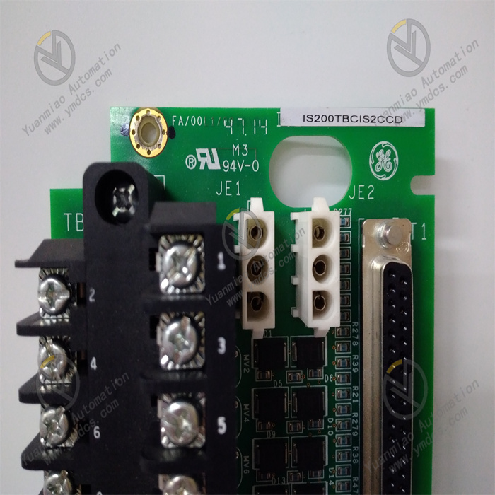
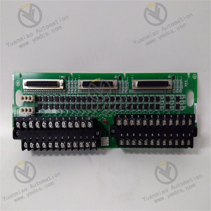
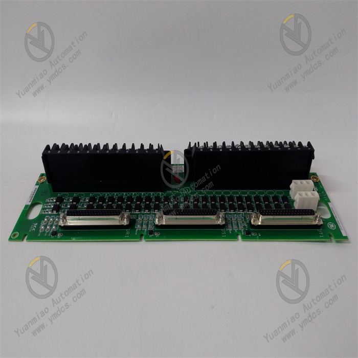
GE IS200TBCIS2CCD
I. Product Overview
GE IS200TBCIS2CCD is a core Input/Output (I/O) module for high-end digital steam turbine control systems, belonging to the Mark VIe series steam turbine control system. It is specifically designed for operational status monitoring, control signal processing, and equipment linkage control scenarios of large-scale steam turbine generator units, and is widely used in industries with strict requirements for steam turbine control accuracy, reliability, and real-time performance, such as thermal power plants, combined cycle power plants, and industrial self-owned power plants.
Adopting a highly integrated hardware architecture, this module integrates core functions including multi-type signal acquisition, high-precision signal conversion, redundant data transmission, and fault self-diagnosis. It can seamlessly interface with GE Mark VIe series controllers, steam turbine actuators (e.g., speed control valves, main steam valves), monitoring sensors (e.g., speed sensors, vibration sensors), and upper-level monitoring systems. It provides a precise I/O signal processing solution for the full operational process of steam turbines—from startup, speed increase, grid connection with load, to shutdown—enabling stable speed control of steam turbines, precise load adjustment, and equipment safety protection.
II. Functional Features
- High-Precision Acquisition and Output of Multi-Type SignalsIt integrates four core signal processing channels: Analog Input (AI), Analog Output (AO), Digital Input (DI), and Digital Output (DO), enabling integrated processing of multi-type signals. The AI channels adopt 16-bit high-precision ADC conversion chips, supporting two signal types (4-20mA/0-10V) with an acquisition accuracy of ±0.1% FS and a configurable sampling frequency (100Hz-1kHz). They can accurately collect key operational parameters of steam turbines, such as speed, vibration, shaft displacement, and main steam pressure/temperature. The AO channels use 14-bit high-precision DAC conversion chips, outputting 4-20mA standard signals with an output accuracy of ±0.2% FS, which can stably drive actuators like speed control valves and regulating valves. The DI channels support two signal types (dry contact/PNP) with a response time of ≤1ms, enabling rapid collection of switching information such as main steam valve status and trip signals. The DO channels adopt relay outputs (250V AC/30V DC, 2A) with an action response time of ≤2ms, which can reliably control auxiliary equipment like oil pumps and fans. Each channel features an independent isolation design with an isolation voltage of ≥2.5kV AC, effectively preventing signal interference between channels.
- Redundancy Fault Tolerance and High-Reliability DesignIt adopts a 1oo2 (1-out-of-2) redundant hardware architecture, with built-in dual independent microprocessing units, dual redundant power interfaces, dual communication interfaces, and dual storage units. The dual microprocessing units synchronously acquire and process signals, and perform real-time cross-verification of data and operational status. Under normal working conditions, the dual units operate in parallel, and after passing data consistency verification, data is uploaded to the controller or control signals are output. When one unit experiences hardware failure or data abnormality, the built-in diagnostic circuit identifies the fault and isolates the faulty unit within 5ms, while the other unit seamlessly takes over all signal processing functions without interruption to signal acquisition and output. The redundant storage units adopt a combined Flash+EEPROM design, with dual storage of channel configuration parameters and calibration data, supporting automatic data recovery after faults to ensure the integrity of system configuration. The module uses a full-metal shielded enclosure with an IP20 protection rating, and its internal circuit adopts an EMC filtering design that complies with the IEC 61000-4 series electromagnetic compatibility standards, enabling it to resist strong electromagnetic interference and adapt to the complex electromagnetic environment of power plants.
- Real-Time Data Transmission and System CollaborationIt is equipped with comprehensive redundant communication interfaces, including 2 standard redundant Ethernet interfaces (supporting EtherNet/IP and Modbus TCP protocols) and 1 GE-specific Genius bus interface. It can achieve high-speed data interaction with Mark VIe controllers, SCADA systems, and HMI (Human-Machine Interface). A priority-based data transmission mechanism is adopted: key data such as steam turbine speed, vibration, and trip signals are transmitted with priority, achieving a maximum transmission rate of 1Gbps and a transmission delay of ≤5ms, ensuring the controller can obtain equipment operational status in real time and issue control commands. It supports collaborative work with steam turbine speed control modules, protection modules, and synchronization modules, realizing inter-module data sharing via the Genius bus with a sharing cycle of ≤1ms, which enables the collaborative execution of control logics such as speed adjustment, load distribution, and fault tripping. It supports online configuration of communication parameters; parameters like IP address, baud rate, and data transmission cycle can be flexibly set via configuration software to adapt to different system topologies.
- Full-Link Fault Diagnosis and Safety ProtectionA three-level intelligent diagnosis system (channel-level, module-level, and system-level) is built, with a diagnosis coverage rate of 99.9%. Channel-level diagnosis monitors the signal amplitude, line on/off status, and drift trend of each I/O channel in real time; when the analog signal drift is ≥±0.5% FS, the digital signal response delay is ≥3ms, or a line open/short circuit occurs, a channel fault alarm is triggered immediately. Module-level diagnosis monitors the operational status of the dual microprocessors, power supply voltage, health status of storage units, and connectivity of communication links, performing self-inspection every 1ms to ensure the normal operation of the module's core components. System-level diagnosis, through linkage with the controller, monitors the consistency between signal acquisition and control command output; when the deviation between the collected data and the command issued by the controller exceeds the threshold, a system-level fault early warning is triggered. Diagnostic information is displayed via front-panel LED indicators and an LCD screen, supporting queries of detailed information such as fault codes, faulty channels, and fault time. Meanwhile, it is uploaded to the operation and maintenance platform via the communication interface, supporting the storage and traceability of 1000 fault history records, with fault codes accompanied by troubleshooting guides and maintenance suggestions. It is equipped with a fail-safe output function; when a severe fault occurs in the module, the DO channels automatically switch to a preset safe state (e.g., shutting down oil pumps, triggering tripping) to ensure the safety of steam turbine equipment.
- Convenient Configuration and Operation & Maintenance ManagementIt supports in-depth parameter configuration via GE-specific configuration software (ToolboxST). The software provides a graphical interface for intuitive configuration of signal types, range limits, calibration parameters, and alarm thresholds for each I/O channel. It has a built-in rich library of signal processing function blocks (e.g., filtering, linearization, scaling) and supports custom signal processing logic. It features an online calibration function: by initiating a calibration command via the software, the module automatically performs zero-point and full-scale calibration for each analog channel with a calibration accuracy of ±0.05% FS, enabling calibration without disassembling the module and simplifying the operation and maintenance process. It supports online program upgrade: firmware upgrade can be completed via the communication interface, and during the upgrade process, it automatically switches to the redundant unit for operation to ensure no interruption to signal acquisition and output. It is equipped with a channel status monitoring function: the input/output values, calibration status, and fault status of each channel can be viewed in real time via the software, supporting real-time recording and trend analysis of channel data to provide data support for predictive maintenance.
- Wide-Range Environmental Adaptability and Flexible InstallationThe module has wide-range environmental adaptability, with an operating temperature range of 0~60℃, a storage temperature range of -40~85℃, and a relative humidity of 5%~95% (no condensation), enabling it to adapt to the environmental conditions of power plants in different regions. It adopts a 35mm standard DIN rail mounting method, compatible with the installation requirements of mainstream control cabinets. With a compact installation size (220×160×80mm), it can save space inside the control cabinet. It supports both vertical and horizontal installation methods; during installation, it can be fixed simply via buckles and fixing screws with an installation torque of 1.2N·m to ensure the module is stable without looseness. The front panel of the module is designed with channel status LED indicators and an LCD screen, facilitating on-site operation and maintenance personnel to intuitively check the module's operational status and fault information, and simplifying on-site debugging and maintenance work.
III. Technical Parameters
| Parameter Category | Parameter Name | Specific Parameters | Unit |
|---|---|---|---|
| Basic Parameters | Model | GE IS200TBCIS2CCD | - |
| Applicable Equipment Type | Steam turbine generator units (100MW-1200MW) | - | |
| Overall Dimensions (L×W×H) | 220×160×80 | mm | |
| Weight | Approximately 1.6 | kg | |
| Core Processing Parameters | Processor Model | TI TMS320F28335 Dual-Core Microprocessor | - |
| Processor Frequency | 150 | MHz | |
| Signal Processing Response Time | ≤1 | ms | |
| Maximum Number of Processable Channels | 32 channels (AI+AO+DI+DO) | Channel | |
| Power Supply Parameters | Power Supply Method | Dual redundant DC power supply | - |
| Input Voltage Range | DC 24V±15% (20.4-27.6V DC) | V DC | |
| Rated Supply Current | ≤1.0A (single-channel power supply, full load) | A | |
| Redundancy Switching Time | ≤5 | ms | |
| Analog Parameters | Number of Analog Input (AI) Channels | 16 channels, independent isolation | Channel |
| AI Signal Type | 4-20mA/0-10V, configurable | - | |
| AI Conversion Accuracy | ±0.1% FS | - | |
| AI Sampling Frequency | 100Hz-1kHz, configurable | Hz | |
| Number of Analog Output (AO) Channels | 8 channels, independent isolation | Channel | |
| AO Signal Type | 4-20mA | - | |
| AO Conversion Accuracy | ±0.2% FS | - | |
| AO Load Capacity | ≤500Ω | Ω | |
| Digital Parameters | Number of Digital Input (DI) Channels | 8 channels, independent isolation | Channel |
| DI Signal Type | Dry contact/PNP, DC 24V | - | |
| DI Response Time | ≤1 | ms | |
| Number of Digital Output (DO) Channels | 8 channels, relay output | Channel | |
| DO Rated Voltage/Current | 250V AC/30V DC, 2A | V/A | |
| DO Action Response Time | ≤2 | ms | |
| Communication Parameters | Standard Communication Interfaces | 2 redundant Ethernet ports, 1 Genius bus port | - |
| Supported Protocols | EtherNet/IP, Modbus TCP, Genius Protocol | - | |
| Maximum Communication Rate | Ethernet: 1Gbps; Genius Bus: 1Mbps | bps | |
| Data Transmission Delay | ≤5 | ms | |
| Data Sharing Cycle | ≤1 | ms | |
| Environmental & Reliability Parameters | Operating Temperature Range | 0~60 | ℃ |
| Storage Temperature Range | -40~85 | ℃ | |
| Relative Humidity | 5%~95% (no condensation) | % | |
| Protection Rating | IP20 | - | |
| Vibration Resistance | 5-150Hz, 1g acceleration (IEC 60068-2-6) | - | |
| Mean Time Between Failures (MTBF) | ≥400,000 | Hour |
IV. Working Principle
The working principle of the GE IS200TBCIS2CCD steam turbine I/O module revolves around six core links: "redundant power supply - signal acquisition/input - signal processing - data transmission - control output - diagnostic protection". Through dual-core redundant processing and a full-link signal management mechanism, it achieves precise monitoring and reliable control of the steam turbine's operational status. The specific working principle is as follows:
- Redundant Power Supply and Power Management LinkAfter two independent DC 24V power supplies are connected to the module via redundant power supply interfaces, they first pass through an EMC filter and a surge suppressor to filter out high-frequency interference and surge impact signals in the power grid, ensuring the stability of the input power supply. They then enter two independent intelligent power management units; each unit is equipped with a high-precision voltage sensor, current sensor, and temperature sensor, which monitor the input voltage, output current, and module temperature in real time and upload the data to the dual microprocessors. The main microprocessor comprehensively determines the main and standby power supplies based on parameters such as voltage stability (fluctuation ≤±5%), current load rate (≤60%), and temperature (≤40℃). By default, the optimal power supply is selected as the main power supply, and the other is in a hot standby state, with electrical isolation achieved via magnetic beads and isolation diodes. When the main power supply voltage is lower than 20.4V, higher than 27.6V, or the load rate is ≥90%, the power switching circuit quickly switches to the standby power supply within 5ms. During the switching process, a super capacitor maintains power supply to the core circuit (duration ≥100ms) to ensure no power interruption. The stabilized power supply is converted by the DC-DC conversion unit into multiple precise voltage outputs (3.3V for the microprocessor core, 5V for the interface circuit, 12V for the drive circuit, etc.), which are supplied to each functional unit after LC filtering. The output ripple is ≤5mV to ensure stable circuit operation.
- Signal Acquisition and Input Processing LinkAnalog signals of the steam turbine (such as speed, vibration, and shaft displacement) are converted into 4-20mA/0-10V standard signals by sensors and then connected to the AI channels; digital signals (such as main steam valve status and trip signals) are directly connected to the DI channels. Analog signals first enter the signal conditioning unit, where they undergo differential amplification, low-pass filtering (with configurable cutoff frequency), and photoelectric isolation to eliminate electromagnetic interference and common-mode noise during transmission. They are then converted into digital signals by a 16-bit high-precision ADC converter, with periodic sampling performed according to the configured sampling frequency (100Hz-1kHz), and the sampled data is temporarily stored in a dual-port RAM. After photoelectric isolation and level conversion, the digital signals have their level status (high/low) determined by a signal detection circuit, and the rise/fall edge times of the signals are recorded, with a response time of ≤1ms. The processed digital status data is also temporarily stored in the dual-port RAM. The dual microprocessors synchronously read the collected data from the RAM and perform data validity verification (e.g., checking if analog signals exceed the range, or if digital signals have jitter). After passing the verification, the data is marked as valid, providing precise input for subsequent signal processing.
- Signal Processing and Data Conversion LinkThe dual microprocessors execute signal processing algorithms on the collected valid data. Analog data undergoes processing such as scaling (converting ADC sampling values into actual physical quantities, e.g., speed in r/min, pressure in MPa), linearization correction (for non-linear sensor signals), and digital filtering (to eliminate high-frequency noise), with a processing accuracy of ±0.1% FS. Digital data undergoes processing such as debouncing (eliminating the impact of signal jitter via delay judgment) and status logic judgment (e.g., determining if the main steam valve is fully open). After processing, the dual microprocessors cross-verify the processing results: if the results are consistent, a valid data frame is generated; if inconsistent, a self-inspection program is immediately activated to locate the faulty microprocessor, isolate the faulty unit, and the normal microprocessor takes over the processing, while triggering a redundancy fault alarm. For control logics requiring local processing (e.g., rapid response to emergency trip signals), the microprocessor directly generates control commands; for signals requiring controller decision-making, the processed data frame is encapsulated into a communication protocol format and waits to be uploaded to the controller.


