Description
GE IS215UCVGM06A
I. Overview
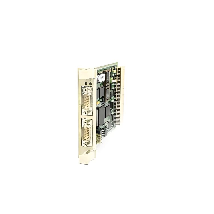
The GE IS215UCVGM06A is a universal control module, an integral part of the Mark VIe series control system. It is specifically designed to meet the precise control requirements of small and medium-sized industrial equipment and process control scenarios. Adopting a highly integrated hardware architecture, this module deeply integrates multi-type signal acquisition, efficient logical operation, accurate control output, and reliable anti-interference design. It enables real-time monitoring of key parameters such as temperature, pressure, rotational speed, and liquid level during equipment operation, as well as rapid execution of control commands and dynamic feedback of system status.
II. Functional Features
The GE IS215UCVGM06A is well-aligned with the actual needs of small and medium-sized industrial control scenarios, integrating GE's core technological accumulation in the industrial control field. It possesses the following core functional features:
- Multi-type Precise Signal Acquisition: Equipped with 6 analog input channels, it supports the acquisition of 4-20mA DC standard current signals, 0-5V DC standard voltage signals, and K-type thermocouple temperature signals, enabling comprehensive capture of various key process and equipment operation parameters in industrial sites. The analog acquisition accuracy reaches ±0.1% FS, with a sampling refresh rate of 100Hz, which can quickly respond to subtle fluctuations in parameters and provide accurate and real-time data support for control decisions. Additionally, it is configured with 12 digital input channels (24V DC) for acquiring discrete signals such as limit switch signals, travel switch signals, solenoid valve feedback signals, and emergency stop signals. The input circuit adopts a 2000V AC photoelectric isolation design, effectively resisting strong electromagnetic interference, surges, and pulse impacts in industrial sites, thus ensuring the stability and accuracy of discrete signal acquisition.
- Flexible and Reliable Control Output: It has 4 analog output channels (configurable 4-20mA DC) with an output accuracy of ±0.2% FS and a load driving capacity of up to 600Ω. These channels can directly drive control components such as small valve positioners, actuators, and frequency converters to achieve precise adjustment of process parameters. It is also equipped with 8 digital output channels, adopting a transistor output mode (output capacity: 1A/24V DC). These channels can be set to normally open or normally closed modes through software configuration, meeting various discrete control needs such as equipment start-stop control, alarm signal output, and solenoid valve on-off control. The output circuit has built-in dual protection mechanisms against overcurrent and short circuits. When an abnormal load is detected, the output circuit can be quickly cut off and locked within 5ms. After the fault is eliminated, the output can be restored through software reset or local operation, effectively protecting the module and controlled equipment.
- Efficient Operation and Flexible Logic Configuration: It is equipped with a GE-customized 32-bit industrial-grade MCU, with a core operating frequency of 300MHz, providing efficient instruction execution capabilities. It can stably run basic control algorithms such as PID (Proportional-Integral-Derivative) adjustment, logic interlocking, and sequential control. The module has built-in 512KB program storage space and 2MB data storage space, which can store multiple sets of control logic schemes for different working conditions. It supports on-line switching of operation modes according to production needs, improving system adaptability. Control logic development is carried out through the GE ToolboxST configuration software, using a drag-and-drop function block programming method. It has a built-in library of basic function blocks such as flow accumulation, temperature compensation, and delay triggering, which greatly reduces development difficulty and shortens the project commissioning cycle.
- Convenient Communication and System Integration: It adopts the Genius Bus communication protocol and is equipped with 2 communication ports that support redundant configuration, with a maximum communication rate of 500kbps, ensuring the real-time and reliability of data transmission between the module and the main controller. It can be directly connected to the Mark VIe control system to realize two-way data interaction with the main controller and other control modules, uploading real-time operation parameters and fault information, and receiving control commands and parameter setting values issued by the main controller. At the same time, it supports compatibility with general industrial communication protocols such as Modbus RTU through a protocol conversion module, meeting the integration needs with third-party small PLCs, SCADA systems, and local monitoring terminals, and realizing centralized monitoring and management of equipment operation status.
- Basic Fault Diagnosis and Redundant Protection: It has a built-in basic self-diagnosis module that monitors the module's power supply status, communication link integrity, input/output channel signal quality, core circuit temperature, and MCU operation status in real time. When faults such as abnormal channel signals, communication interruption, excessive power supply voltage fluctuation, and overheating of core components are detected, an alarm can be triggered within 10ms. Detailed information including fault codes, fault locations, and fault types is uploaded through the communication interface, and the corresponding LED fault indicator on the front of the module is lit, providing clear guidance for operation and maintenance personnel to quickly locate fault points. It supports module-level hot redundant configuration. The active and standby modules realize real-time synchronization of collected data, control logic, and operation status through a dedicated synchronization interface. When the active module fails, the standby module can automatically switch to the working state seamlessly within 15ms, ensuring no interruption of the control process and improving the continuity of system operation.
- Industrial-grade Compact and Reliable Design: It adopts industrial-grade components with a wide temperature range. The operating temperature range covers -30℃ to 70℃, and the storage temperature range is -40℃ to 85℃, making it adaptable to various complex environments such as high-temperature workshops, low-temperature storage auxiliary equipment, and outdoor simple control rooms. The module adopts a compact circuit layout and is matched with an integrated high-efficiency heat sink, which can realize effective heat dissipation of core components without additional cooling fans, reducing equipment operation noise and maintenance costs. The shell is made of flame-retardant ABS plastic, with an IP20 protection level. It has certain anti-vibration performance (5-500Hz, 1g acceleration) and anti-impact performance (10g, 11ms), and has passed the IEC 61000-6-2/4 industrial electromagnetic compatibility standard and UL safety certification. The Mean Time Between Failures (MTBF) is more than 120,000 hours.
- Convenient Configuration and Operation & Maintenance Management: It supports the completion of the entire process operations such as module parameter configuration, control logic programming, fault diagnosis, data monitoring, and firmware upgrade through the GE ToolboxST configuration software. The software has a built-in offline simulation function, which can verify the control logic without connecting to hardware, reducing the risk of on-site commissioning. The front of the module is equipped with a 1.5-inch monochrome LCD display and 4 operation buttons, which can display the parameters of each input/output channel, module operation status, and fault codes in real time locally. It supports local parameter fine-tuning, control mode switching, and fault reset operations through the buttons. It also supports on-line debugging and parameter modification, and configuration updates can be completed without disconnecting the system power supply, greatly improving operation and maintenance efficiency and reducing equipment downtime.
III. Technical Parameters
| Parameter Category | Parameter Name | Specific Parameters | Unit |
|---|---|---|---|
| Basic Parameters | Model | GE IS215UCVGM06A | - |
| Overall Dimensions (L×W×H) | 180×140×70 | mm | |
| Weight | Approximately 0.9 | kg | |
| Installation Method | Rack-mounted (compatible with GE Mark VIe standard cabinets and small industrial cabinets) | - | |
| Power Supply Parameters | Power Supply Voltage | DC 24V (±10%) | V |
| Rated Power Supply Current | 2A | A | |
| Power Consumption | ≤48W | W | |
| Power Supply Redundancy | Supports redundant switching of dual independent power inputs | - | |
| I/O Parameters | Analog Input Channels | 6 channels, 4-20mA DC/0-5V DC/K-type thermocouple, ±0.1% FS accuracy | channel |
| Digital Input Channels | 12 channels, 24V DC, 2000V AC photoelectric isolation | channel | |
| Analog Output Channels | 4 channels, configurable 4-20mA DC, ±0.2% FS accuracy, 600Ω load | channel | |
| Digital Output Channels | 8 channels, transistor output, 1A/24V DC | channel | |
| Isolation Voltage | 2000V AC (mutual isolation between input/output/power supply) | V | |
| Sampling Refresh Rate | 100Hz (analog input), 1ms (digital input) | Hz/ms | |
| Communication & Reliability Parameters | Communication Interface | 2 Genius Bus channels, supporting redundant configuration | channel |
| Communication Rate | 500kbps | bps | |
| Operating Temperature Range | -30~70 | ℃ | |
| Storage Temperature Range | -40~85 | ℃ | |
| Mean Time Between Failures (MTBF) | ≥120,000 | hour |
IV. Working Principle
The GE IS215UCVGM06A realizes precise control of small and medium-sized industrial equipment and processes based on a closed-loop control process of "signal acquisition - data processing - logical operation - command output - communication interaction - fault protection". Its specific working principle is as follows:
- Multi-type Signal Acquisition Link:Various sensor signals in the industrial field (such as 4-20mA signals output by pressure sensors, K-type thermocouple signals for temperature monitoring, and 24V DC signals output by limit switches) are connected to the corresponding input channels of the module through dedicated cables. The analog input channels have built-in high-precision signal conditioning circuits, which perform filtering, amplification, and linearization processing on the input analog signals. For K-type thermocouple signals, automatic cold-junction compensation is carried out to effectively eliminate errors caused by on-site electromagnetic interference, temperature drift, and other factors. The conditioned analog signals are converted into digital signals through a 16-bit high-precision A/D converter to complete the digital conversion of analog quantities. The discrete signals connected to the digital input channels first undergo electrical isolation through a photoelectric isolation circuit to prevent external interference signals from entering the module. Then, the signals are shaped through a Schmitt trigger to ensure that the edges of the input digital signals are clear and free of jitter, thus ensuring the integrity of discrete signals.
- The collected digital signals (including digital signals converted from analog quantities and shaped digital signals) are transmitted to the core control unit (32-bit MCU) through the high-speed data bus inside the module, completing the signal acquisition and transmission process. Among them, the analog acquisition delay is ≤8ms, and the digital response time is ≤1ms, which can meet the real-time data requirements of small and medium-sized industrial control scenarios.
- Data Processing and Logical Operation Link:After receiving the collected digital signals, the core MCU first performs calibration and scaling conversion processing, converting the original digital signals into corresponding actual physical quantities (for example, converting 4-20mA current signals into pressure values of 0-10MPa, and converting digital signals of K-type thermocouples into temperature values of 0-400℃). Then, according to the control logic preset through the GE ToolboxST configuration software (such as PID adjustment logic, equipment start-stop interlock logic, parameter over-limit alarm logic, etc.), the MCU compares and calculates the real-time collected physical quantity parameters with the preset control target values to generate accurate control commands. For example, when the water pump outlet pressure is detected to be lower than the preset value, the MCU generates a command to increase the output signal through PID calculation to control the frequency converter to increase the water pump speed; when the reactor temperature is detected to exceed the upper limit, it immediately generates a digital command to turn off the heating device and an alarm signal.
- While performing data processing and logical operations, the MCU runs a self-diagnosis program synchronously, monitoring key parameters such as the module's power supply voltage, communication link signal strength, signal status of each input/output channel, core circuit temperature, and its own operation status in real time, and comparing them with the preset normal threshold range. If an abnormal parameter is detected (such as the power supply voltage exceeding the ±10% range, communication link interruption, or no change in channel signals), fault information is immediately generated, and the fault type and fault location are marked.
- Control Command Output Link:The control commands generated by the core MCU are divided into analog control commands and digital control commands according to their types, which are transmitted to the corresponding output channels respectively. The analog control commands are first converted into standard analog current signals of 4-20mA through a 16-bit D/A converter, and then amplified through a power drive circuit and output to the controlled executive components (such as valve positioners, frequency converters). The precise control of process parameters is realized by adjusting the actions of the executive components. The digital control commands control the on and off of the transistors through the drive chip, and output the corresponding switch signals to the controlled equipment (such as feed pumps, alarm lights, solenoid valves), realizing discrete control functions such as equipment start-stop control and alarm signal output.
- The output channel has built-in dual protection circuits against overcurrent and short circuits, which monitor the current status of the output circuit in real time. When an overcurrent (exceeding 1A) or short-circuit fault is detected in the output circuit, the protection circuit acts immediately to quickly cut off the output circuit and lock the output state. At the same time, the fault information is fed back to the core MCU to prevent the fault from expanding and causing damage to the module or controlled equipment. After the fault is eliminated, the output function can be restored only through the GE ToolboxST configuration software or the local operation buttons of the module for reset.
- Communication Interaction and Data Synchronization Link:The module establishes a stable communication link with the Mark VIe main controller through the Genius Bus communication interface. It uploads real-time collected physical quantity parameters, module operation status information, and fault information to the main controller according to the preset communication cycle (configurable 5-50ms), and at the same time receives control logic update commands and parameter setting adjustment commands issued by the main controller. For scenarios that require integration with third-party systems, the module converts the Genius Bus protocol into general protocols such as Modbus RTU through a protocol conversion module, realizing data interaction with third-party PLCs and SCADA systems and meeting the needs of centralized monitoring.
- When the module adopts redundant configuration, the active and standby modules establish a data synchronization link through a dedicated synchronization interface. The active module synchronizes the collected data, control commands generated by calculation, and its own operation status to the standby module in real time to ensure data consistency between the active and standby modules. The active module sends a heartbeat signal to the standby module every 1ms, and the standby module monitors the heartbeat status of the active module in real time, providing a basis for redundant switching.
- Redundant Switching and Fault Handling Link:When the active module fails (such as communication interruption, power failure, abnormal core MCU, etc.), the standby module detects the loss of the active module's heartbeat signal or fault information within 15ms, and immediately triggers the redundant switching mechanism, automatically switching to the working state, taking over all control tasks and communication tasks of the active module, ensuring no interruption of the control process and guaranteeing continuous operation of the equipment. The faulty active module automatically enters the isolation state to avoid affecting other parts of the system.
- After the module detects a fault, while uploading the fault information to the main controller, it lights the indicator light corresponding to the fault type (such as power fault light, communication fault light, channel fault light) through the LED fault indicator on the front of the module, and displays the fault code, fault location, and fault cause description on the local LCD display. Operation and maintenance personnel can quickly locate the fault point through the information displayed by the indicator lights and the LCD, improving the efficiency of fault troubleshooting.