Description
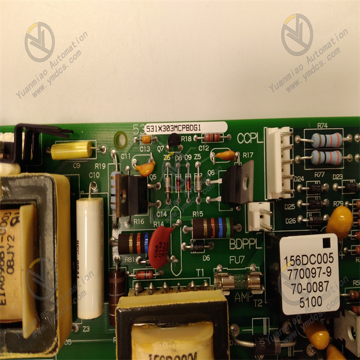
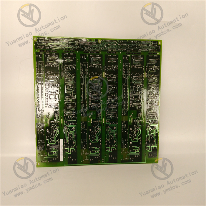
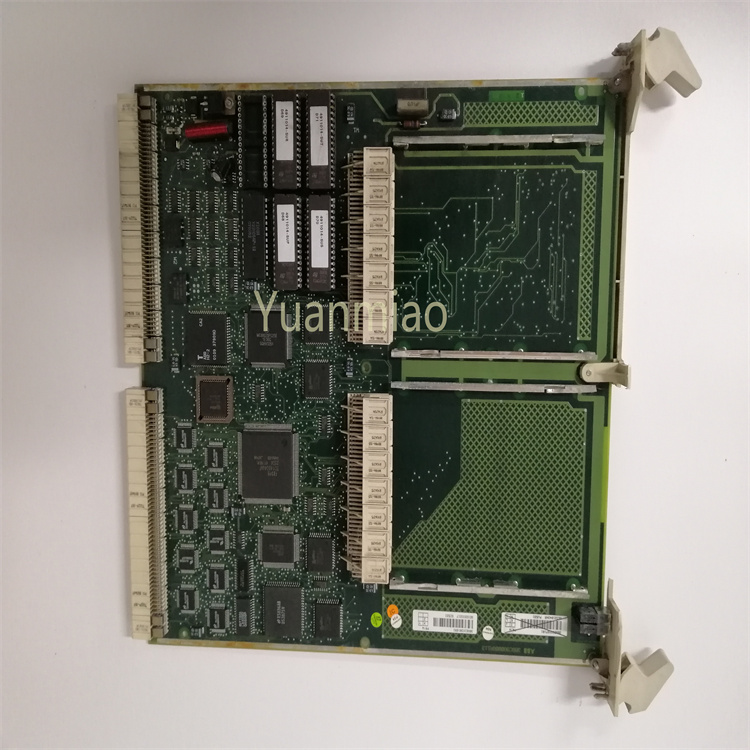
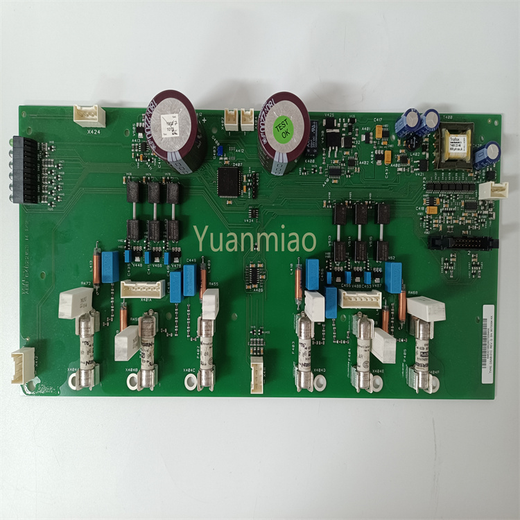
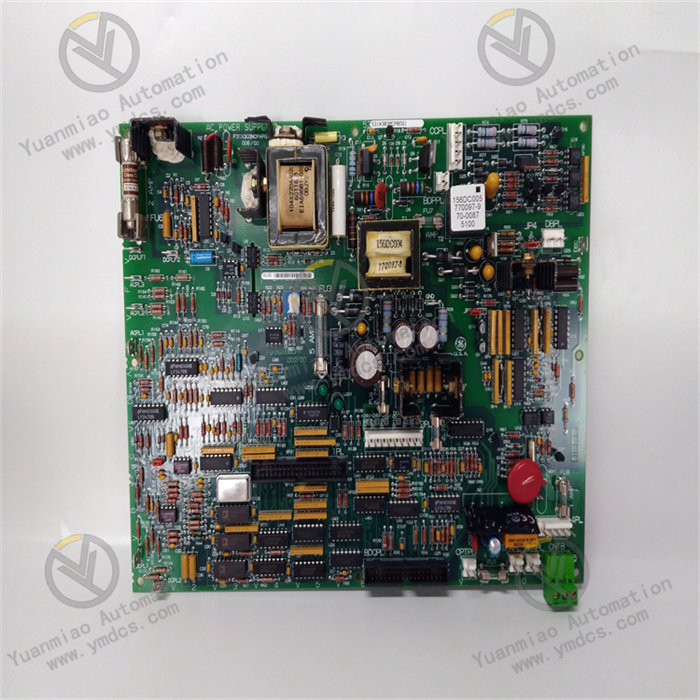
GE 531X303MCPBDG1
The GE 531X303MCPBDG1 is a digital input/output (I/O) module belonging to the core I/O component family of the GE Mark VIe Distributed Control System (DCS). It is specifically designed for gas turbines, steam turbines, combined-cycle power generation, and other industrial process control applications. Its core function is to achieve accurate acquisition and reliable output of digital signals in industrial fields: it collects digital input signals from on-site sensors (such as limit switches, pressure switches, and emergency stop buttons), transmits them to the Mark VIe controller for logical operations, and simultaneously receives control commands issued by the controller to drive the actions of actuators (such as solenoid valves, contactors, and alarm indicators). This provides critical signal interaction support for the safe and stable operation of units or process equipment.
This module adopts a modular design, featuring high compatibility and expandability. It can be seamlessly integrated into the I/O rack of the Mark VIe control system and supports hot swapping and online maintenance. Complying with industrial-grade reliability standards, it offers excellent electromagnetic interference (EMI) resistance, a wide operating temperature range, and redundant design capabilities, enabling it to adapt to the harsh operating requirements of industrial environments such as power generation and petrochemical industries. Through high-speed communication with the controller via GE's dedicated control protocol, it ensures the real-time performance and accuracy of signal transmission, making it one of the key components for building highly reliable industrial control systems.
Seamless Integration with Mark VIe System, Excellent Compatibility: The module adopts the standard hardware architecture and communication protocol of the Mark VIe series. It can be directly inserted into any compatible slot of the Mark VIe standard I/O rack without additional adapters or drivers. Through the rack backplane bus, it achieves high-speed data interaction with the Mark VIe controller (e.g., IC695CPU310) at a communication rate of 1Gbps, ensuring the real-time performance of input signal acquisition and output command execution. It supports the GE Proficy Machine Edition configuration software, allowing users to complete channel configuration, parameter setting, and fault diagnosis via a graphical interface. It works in synergy with other system components (such as analog modules and communication modules) to build a complete distributed control solution.
16-Input & 8-Output Hybrid Channels, Adaptable to Diverse Scenarios: Integrating 16 digital input channels and 8 digital output channels, it forms an integrated "acquisition-control" signal processing unit. It can directly connect to on-site sensors and actuators, reducing the number of modules and system wiring. The input channels support two signal types (dry contact and wet contact), and the signal mode of each channel can be independently configured via software, adapting to different types of input devices such as limit switches, emergency stop buttons, and pressure switches. The output channels use transistor-type outputs with configurable NPN/PNP modes, capable of driving various actuators such as solenoid valves, contactors, and alarm lights without additional driver modules, simplifying system integration.
High-Reliability Isolation Design, Outstanding Anti-Interference Performance: Adopting comprehensive electrical isolation technology, independent isolation is implemented between input/output channels, between each channel and the rack backplane, and between channels and the power supply. The isolation voltages reach 1500VAC/1min (inter-channel) and 2500VAC/1min (channel-to-backplane), effectively blocking interference from on-site ground loops, electromagnetic radiation, and power fluctuations on signal transmission. The input channels are equipped with hardware filtering circuits and surge suppression components to filter high-frequency noise and transient pulse interference, ensuring the stability of input signals. The output channels feature overcurrent protection and short-circuit protection: when the load current exceeds 2A or a short circuit occurs, the module automatically cuts off the output of the faulty channel to avoid module damage, and can automatically recover or be manually reset after the fault is resolved.
Hot-Swapping & Redundancy Support, Doubled Availability: It supports hot swapping, allowing the module to be directly inserted or removed for replacement or maintenance while the Mark VIe system remains in operation and the controller continues to run. When the module is removed, the controller automatically identifies the status of the corresponding channels, marks them as "faulty," and executes preset safety logic (e.g., setting output channels to a safe state). After inserting a new module, the system automatically completes initialization and synchronizes configuration parameters, quickly restoring channel functions without restarting the controller, significantly reducing maintenance downtime. It also supports I/O channel redundancy configuration: critical signals can be connected to channels of two different modules to achieve "dual-acquisition" or "dual-output" redundancy, improving system reliability.
Accurate Response & Flexible Configuration, Efficient Control: The default response time of the input channels is ≤1ms, and the range can be flexibly configured between 0.1~10ms via configuration software. This enables rapid capture of status changes of on-site sensors (such as the instantaneous triggering of emergency stop buttons), providing fast signal feedback for critical control scenarios. The output channels use high-speed transistor drives with a command response time of ≤0.5ms, enabling rapid execution of control commands issued by the controller and ensuring the timeliness of actuator actions. Via the Proficy Machine Edition software, the filtering time and logic polarity (high-level active/low-level active) of each input channel, as well as the action mode (pulse output/hold output) of each output channel, can be independently configured to adapt to the signal characteristics and control requirements of different on-site devices.
Full-Process Diagnosis & Fault Early Warning, Convenient Operation & Maintenance: It is equipped with comprehensive online diagnosis functions, capable of real-time monitoring of the operating status of the module's internal core components (logic circuits, power supply, communication interfaces), input channels (open circuit, short circuit, overvoltage), and output channels (overcurrent, short circuit, transistor fault). Diagnostic information includes fault type, faulty channel, and fault occurrence time, which can be remotely viewed via the diagnostic interface of the Proficy Machine Edition software or locally displayed through the LED indicators on the front of the module (power light, operation light, channel status light, fault light), facilitating maintenance personnel to quickly locate fault points. It also supports fault early warning: when potential fault signs such as channel signal drift or power voltage fluctuation are detected, early warning signals are issued in advance to support predictive maintenance.
Industrial-Grade Reinforced Design, Strong Environmental Adaptability: Using industrial-grade components and an all-metal housing design, it offers excellent heat dissipation performance and mechanical strength. It can adapt to an operating temperature range of -10~60℃ and operate stably in high-temperature, dusty industrial environments such as power generation workshops and chemical plants. It has passed the IEC 61000-4 series EMI resistance tests, featuring strong anti-static, anti-radio frequency interference, and anti-pulse group interference capabilities, and can maintain stable signal transmission near high-voltage equipment and high-power motors. The module has passed the vibration and shock tests in accordance with the MIL-STD-810G standard, with 3g vibration resistance and 15g shock resistance, adapting to the vibration environment during unit operation.
As the core of signal interaction in the Mark VIe control system, the GE 531X303MCPBDG1 module realizes accurate processing and reliable control of digital signals through a core workflow of "initialization & configuration loading → signal acquisition → verification & transmission → command execution → diagnostic feedback." The specific workflow is as follows:
Module Initialization & Configuration Loading: After the module is installed in the Mark VIe I/O rack and powered on, it automatically initiates the initialization process. First, it performs a hardware self-test to check the integrity of logic circuits, input/output interfaces, backplane communication interfaces, and power modules. After passing the self-test, it establishes communication with the controller via the backplane bus and receives configuration parameters (such as channel type, response time, filtering parameters, and logic polarity) issued by the controller. Upon completion of initialization, the module sends a "ready" signal to the controller, the LED indicators show a "normal operation" status, and the module enters the working mode. If the self-test or configuration loading fails, a fault alarm is triggered immediately, the output channels are set to a safe state, and fault information is uploaded to the controller.
Input Signal Acquisition & Verification: After on-site sensor signals are connected to the corresponding input channels, the wet contact channels are powered by the isolated power supply inside the module, while the dry contact channels directly collect on-off signals. The signals are filtered to remove noise by hardware filtering circuits, then amplified and shaped by the signal conditioning unit to be converted into standard digital signals. The internal logic processing unit of the module performs double verification (signal consistency verification and range verification) on the digital signals. If the verification passes, the signals are determined to be valid, isolated, and then transmitted to the controller via the backplane bus. If the verification fails (e.g., the signal exceeds the range, or three consecutive collected signals are inconsistent), the channel is marked as faulty, diagnostic information is uploaded immediately, and the corresponding fault indicator is illuminated.
Output Command Execution & Status Feedback: After receiving the input signals and performing logical operations, the controller issues output control commands to the module via the backplane bus. Upon receiving the commands, the module processes them through isolation circuits and signal amplification units, then drives the transistors of the corresponding output channels to act (in NPN mode, the transistor outputs a low level when turned on; in PNP mode, it outputs a high level when turned on), thereby controlling the action of the actuator. At the same time, the module monitors the conduction status of the transistors and the load current in real time through the output feedback circuit, and transmits the action results (e.g., whether conduction is in place, whether the load current is normal) back to the controller, forming a closed-loop control of "command → execution → feedback." If an overcurrent or short-circuit fault is detected, the output of the faulty channel is cut off immediately, fault information is uploaded, and an alarm is triggered.
Real-Time Diagnosis & Fault Handling: During operation, the module continuously performs multi-level diagnosis: ① Hardware diagnosis: periodically checks the stability of logic circuits, power voltage, and communication links; ② Channel diagnosis: real-time monitors the signal integrity of input channels and the load status of output channels; ③ Communication diagnosis: verifies the communication data frames with the controller to ensure error-free data transmission. When a fault is diagnosed, three actions are executed immediately: ① Reset the output channels to a preset safe state (e.g., full shutdown); ② Upload detailed fault codes to the controller via the backplane bus; ③ Illuminate the corresponding fault indicator on the front of the module. If redundant channels are configured, the controller automatically switches to the redundant channels for operation to ensure uninterrupted control.
![]()


