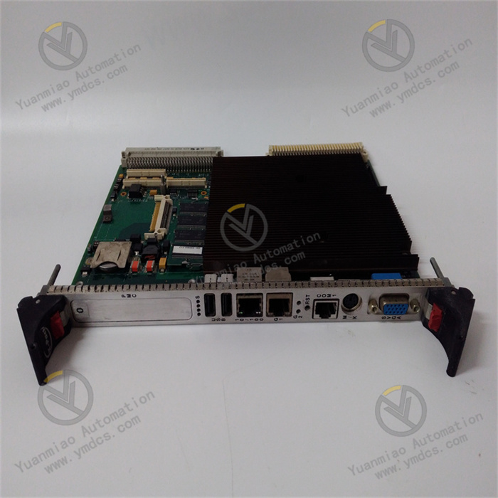
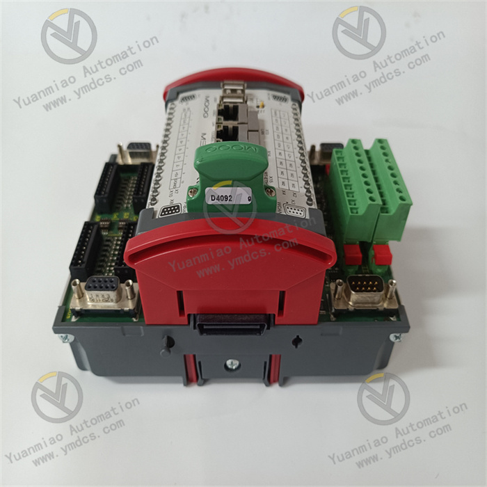
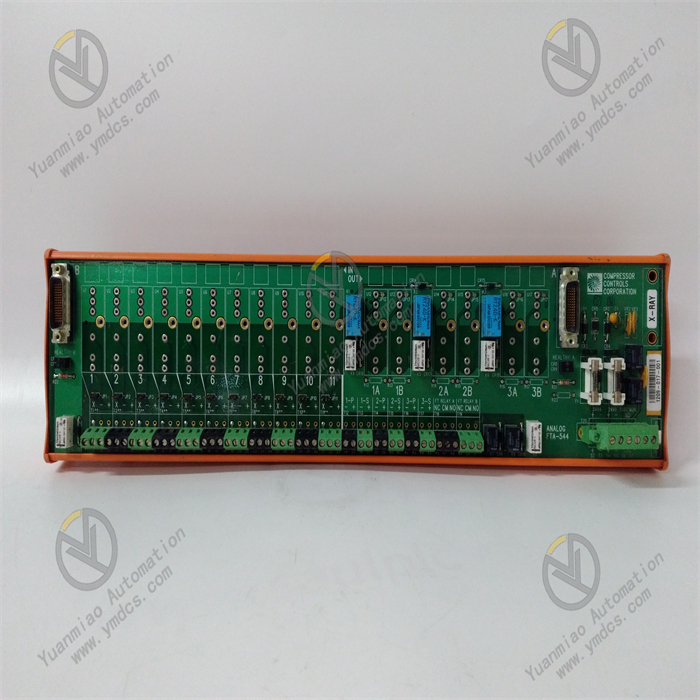
GE 531X307LTBAHG1 | LAN Terminal Board 531X Series

GE 531X307LTBAHG1 | LAN Terminal Board 531X Series

Brand: General Electric

Product ID: 531X307LTBAHG1

Condition: New / used

Terms of payment: Paypal、T/T 、Western Union

Category:

Description

GE 531X307LTBAHG1

1. Overview


The GE 531X307LTBAHG1 is a signal I/O module belonging to classic industrial control systems such as GE Mark VIe or Fanuc Series 90-30. Its core positioning is "the core for multi-type signal acquisition, logic operation, and control command execution in embedded control systems under harsh industrial environments". It mainly serves fields with extremely high requirements for signal acquisition accuracy, control response speed, and environmental adaptability, including power generation equipment monitoring (e.g., steam turbines, gas turbines), metallurgical rolling mill control, chemical process regulation, and rail transit equipment signal processing. It undertakes the full-process key tasks of "on-site analog/digital signal acquisition - signal conditioning and conversion - logic operation and interlock control - control command output - equipment status feedback".


With core advantages of "mixed-signal compatible acquisition + industrial-grade high-reliability hardware + wide-temperature and harsh-environment-resistant design + full-system adaptation", this module has irreplaceable value in scenarios such as the upgrading of old industrial control systems (e.g., replacing traditional discrete I/O components) and the construction of new embedded control nodes (e.g., distributed control units). Its core function is to solve the three major pain points in industrial control: "difficulty in multi-type signal compatibility", "signal distortion in complex environments", and "control command response delay". Through high-precision signal conditioning circuits, standardized system interfaces, and enhanced protection design, it realizes accurate on-site signal acquisition (analog accuracy ≤ ±0.1% F.S., digital response ≤ 1ms) and efficient control (output response ≤ 5ms), avoiding production interruptions caused by inaccurate signal processing or control delays (the loss of a single interruption can reach hundreds of thousands of yuan) and ensuring the continuous and stable operation of industrial systems.


2. Technical Parameters


2.1 Signal Acquisition and Output Parameters


CategorySpecific Parameters
Analog Input ChannelsNumber of channels: 8 channels, selectable between single-ended/differential (switchable via hardware jumpers);
Input signal types:
- Current: 4-20mA DC (compatible with 2-wire/4-wire sensors);
- Voltage: 0-10V DC, 1-5V DC;
Acquisition accuracy: ±0.1% F.S. (at 25℃), temperature drift ≤ 50ppm/℃ (-40℃~+70℃);
Signal conditioning: Built-in RC filter circuit (cutoff frequency 1kHz), signal amplification circuit (adjustable gain), signal-to-noise ratio ≥ 70dB;
Isolation method: Electrical isolation between channels (isolation voltage ≥ 2500Vrms), isolation between channels and control circuit (isolation voltage ≥ 2500Vrms).
Digital Input ChannelsNumber of channels: 16-channel isolated digital input;
Input type: Compatible with dry contacts/wet contacts;
- Dry contacts: Passive contacts (contact capacity ≥ 5mA@24V DC);
- Wet contacts: Active signals (voltage range 24V DC±10%, input current 5-30mA);
Response time: ≤ 1ms (from signal trigger to module recognition);
Isolation method: Isolation between channels (isolation voltage ≥ 2500Vrms), supporting ground loop interference suppression.
Digital Output ChannelsNumber of channels: 8-channel isolated digital output;
Output type: Relay output (normally open contacts);
Contact capacity: 2A/250V AC, 2A/30V DC (resistive load); 1A/250V AC, 1A/30V DC (inductive load);
Response time: ≤ 5ms (from command issuance to contact action);
Isolation method: Isolation between output circuit and control circuit (isolation voltage ≥ 2500Vrms), preventing reverse breakdown caused by load voltage.

2.2 System Interface and Operation Parameters


CategorySpecific Parameters
System Bus InterfaceCompatible buses: GE Genius Bus, PROFIBUS DP (switchable according to system configuration);
Bus rate: Up to 10Mbps (PROFIBUS DP mode), data transmission delay ≤ 15ms;
Bus function: Supports slave mode, receives control commands from upper computers (e.g., GE Mark VIe controller, Fanuc 90-30 PLC), and uploads collected signals and module status;
Address configuration: Bus address (configurable from 1 to 32) set via DIP dip switches on the top of the module, supporting address conflict detection.
Operation and StorageProcessor: Built-in 16-bit industrial-grade microprocessor (GE customized model, main frequency ≥ 40MHz);
Operation cycle: ≤ 10ms (completes 8-channel analog acquisition, 16-channel digital recognition, and 8-channel output command operation in a single cycle);
Supported logic functions: AND/OR/NOT logic, delay (adjustable from 0.1s to 100s), pulse counting (maximum frequency 1kHz), analog threshold comparison (e.g., over-temperature alarm), multi-signal interlock control;
Storage capacity: 128KB EEPROM (stores configuration parameters and logic programs, data retained permanently after power failure); 32KB RAM (running cache).
External InterfacesSignal interfaces: 3 groups of Phoenix terminals (5.08mm pitch) on the front panel, corresponding to analog input (terminals 1-16), digital input (terminals 17-32), and digital output (terminals 33-40) respectively; screw-fastened wiring (torque 0.4N・m), contact resistance ≤ 30mΩ;
Status indicators: 8 analog input indicators (green, steady on = normal signal), 16 digital input indicators (green), 8 digital output indicators (red), 1 power indicator (yellow), 1 bus indicator (blue, blinking = normal communication);
Debugging interface: 1 9-pin RS-232 serial port (baud rate 9600bps, data bits 8, stop bit 1), used for parameter configuration and program download.

2.3 Physical and Environmental Parameters


CategorySpecific Parameters
Physical SpecificationsDimensions: 175mm (length) × 110mm (width) × 30mm (height), conforming to GE standard I/O module dimensions, compatible with 35mm DIN rail mounting;
Weight: Approximately 280g;
Mounting method: DIN rail clamping (horizontal/vertical optional); mounting clearance: ≥ 15mm above and below (for heat dissipation), ≥ 8mm on left and right (for wiring).
Environmental AdaptabilityOperating temperature: -40℃~+70℃ (industrial wide temperature range), no preheating required for startup at -40℃ (startup time ≤ 25s);
Storage temperature: -55℃~+85℃;
Humidity: 5%~95% RH (non-condensing, complying with IEC 60068-2-3 standard);
Vibration resistance: 10g (10Hz-2000Hz, complying with IEC 60068-2-6), adapting to vibration transmission from equipment such as fans and compressors;
Shock resistance: 50g (1ms pulse, complying with IEC 60068-2-27), withstanding shocks during equipment handling and maintenance;
Electromagnetic Compatibility (EMC): Complying with EN 55022 Class A and EN 55024 standards; ESD protection: ±15kV (air discharge)/±8kV (contact discharge); radio frequency immunity: 20V/m (80MHz-1GHz).

2.4 Power Supply and Reliability Parameters


CategorySpecific Parameters
Power Supply RequirementsSupply voltage: 24V DC (±15%), input range 20.4V-27.6V DC;
Operating current: ≤ 300mA (full configuration, all channels activated);
Power protection: Overvoltage protection (automatic shutdown when ≥ 30V DC), overcurrent protection (current limiting triggered when ≥ 400mA), reverse polarity protection (preventing reverse connection of positive and negative poles), built-in self-recovering fuse (1A).
Reliability IndicatorsMean Time Between Failures (MTBF) ≥ 250,000 hours (Telcordia SR-332 standard, at 25℃);
Design life: ≥ 12 years;
Key components (operational amplifiers, isolation chips, relays): Adopting industrial-grade wide-temperature models (-40℃~+85℃);
Relay contact life: ≥ 1,000,000 times (under rated load);
Fault diagnosis: Built-in hardware-level fault detection, supporting power supply abnormality, bus interruption, and channel fault detection; fault codes reported via indicators and bus (e.g., "E02 = Analog channel fault", "E05 = Bus disconnected").


3. Functional Features


3.1 Mixed-Signal Compatibility, Simplifying System Integration

  • One-stop processing of multi-type signals: Integrates analog (4-20mA, 0-10V) and digital (dry/wet contact) acquisition channels, enabling simultaneous connection to different types of peripherals such as temperature sensors, pressure transmitters, proximity switches, and photoelectric sensors. No additional independent acquisition modules are required, reducing the number of system components by 50% compared with discrete solutions, and lowering integration costs and failure rates. For example, in chemical reactor control, it can simultaneously collect analog signals of reaction temperature (4-20mA) and pressure (0-10V), as well as digital signals such as valve switching and motor operation status, realizing "temperature + pressure + equipment status" coordinated control.

  • Flexible signal conditioning and adaptation: Analog channels support single-ended/differential switching; in differential mode, the common-mode rejection ratio is ≥ 80dB, which can effectively suppress interference signals generated by long-distance wiring (≤ 100m). It supports custom signal ranges (configured via debugging software) and is compatible with sensors of different specifications (e.g., 0-5V liquid level sensors, 2-10mA flow sensors). Diverse acquisition needs can be met without replacing the module, improving system adaptation flexibility.


3.2 Industrial-Grade Stable Operation, Adapting to Harsh Environments

  • Wide-temperature and anti-interference design: Core components adopt wide-temperature models (-40℃~+85℃); the circuit board is coated with nano-level three-proof paint (waterproof, dustproof, anti-corrosive), enabling stable operation in scenarios such as outdoor power control cabinets in Northeast China (winter temperature -35℃), coastal chemical workshops (high humidity and high salt spray), and metallurgical high-temperature workshops (ambient temperature 65℃). The annual failure rate of the module is ≤ 0.3%. The power module is equipped with an EMC filter circuit (common-mode rejection ratio ≥ 75dB); when installed near high-power frequency converters (above 200kW), the analog acquisition error is still ≤ 0.2% F.S., and there is no misjudgment of digital signals.

  • Enhanced isolation and protection: All signal channels adopt 2500Vrms electrical isolation to avoid crosstalk between different signals and ground loop interference (e.g., signal distortion caused by equipment ground potential difference). Digital output relays adopt sealed packaging (protection class IP65), and contacts are gold-plated (thickness ≥ 0.5μm). In the control of mining equipment with heavy dust, the contact oxidation rate is ≤ 0.1μm/year, ensuring long-term reliable operation.


3.3 Efficient Operation and Precise Control, Improving System Performance

  • Fast signal response and operation: The analog acquisition accuracy reaches ±0.1% F.S., which can accurately capture small signal changes (e.g., 0.5℃ fluctuation of steam turbine bearing temperature). The digital input response time is ≤ 1ms, which can quickly identify emergency signals such as emergency stop buttons and equipment faults. Combined with the 10ms operation cycle of the 16-bit microprocessor, the total delay of control commands from signal acquisition to output execution is ≤ 15ms, meeting the real-time requirements of industrial control (e.g., rolling mill thickness control, elevator safety protection).

  • Intelligent logic and interlock control: Built-in rich logic operation functions, supporting multi-signal interlock (up to 8-channel input signal linkage), which can realize "condition trigger - command output" automatic control (e.g., "temperature ≥ 100℃ + pressure ≥ 0.8MPa" interlock to close the feed valve). It does not rely on the computing power of the upper computer, reducing system communication load and delay risks. At the same time, it supports analog threshold alarms (e.g., liquid level exceeding the upper limit triggers an audible and visual alarm), realizing rapid local response and improving control safety.


3.4 Full-System Adaptation and Convenient Operation & Maintenance, Reducing Costs

  • Cross-system compatibility and upgrading: Perfectly compatible with GE-series control systems such as GE Mark VIe and Fanuc 90-30, supporting GE Proficy Machine Edition programming software. Module function blocks (AI, DI, DO function blocks) can be directly called, shortening the programming cycle from 3 days (traditional solution) to 1 day. It is compatible with GE old-generation I/O modules (e.g., 531X305 series), enabling direct replacement of old modules while retaining the original wiring and programs, reducing the upgrade cost by 60%. In addition, it supports interconnection with third-party systems such as Siemens and Rockwell via PROFIBUS DP bus, solving the problem of cross-brand system integration.

  • Visual operation & maintenance and fault diagnosis: 33 status indicators are installed on the front panel, allowing on-site personnel to quickly judge the signal status through the indicators (e.g., "analog input indicator not on" indicates a sensor or channel fault; "output indicator on but load not working" indicates a relay or load problem). The debugging serial port supports reading real-time data (acquisition values, output status, fault logs) via terminal software. The built-in fault log can record the latest 50 fault information (including fault type and occurrence time), shortening the fault location time from an average of 2 hours to 30 minutes and reducing shutdown losses.


4. Common Faults and Solutions


Common Fault PhenomenaPossible CausesSolutions
Distortion or fluctuation of all analog acquisition data1. Excessive fluctuation of power supply voltage (beyond 20.4V-27.6V);
2. Unshielded signal cables or poor grounding;
3. Fault in the module's analog conditioning circuit
1. Use a multimeter to detect the power supply voltage and ensure it is within the range of 24V DC±15%. If the fluctuation is large, install a 24V DC voltage stabilizer (output accuracy ±1%) and an EMC filter (insertion loss ≥ 30dB@100kHz);
2. Replace with industrial-grade shielded cables, ensure the shield layer is grounded at one end (grounding resistance ≤ 4Ω), and avoid parallel routing with high-voltage cables (≥220V AC) (spacing ≥ 30cm);
3. Cross-test: Connect a normal sensor to the faulty module. If the data is still distorted, the module is determined to be faulty, and replace it with the same model (original accessories are preferred).
Failure to recognize a single digital input channel, indicator not on1. Sensor fault (e.g., no output from proximity switch);
2. Loose wiring or cable breakage;
3. Fault in the module's channel isolation circuit
1. Disconnect the wiring and use a multimeter to test the sensor: In wet contact mode, the output of the sensor should be 24V DC±10% after power-on; in dry contact mode, the resistance should be ≤ 1Ω when the contact is closed. If the sensor has no output, replace the sensor;
2. Check the tightness of terminal screws (torque 0.4N・m), and use the continuity test function of a multimeter to detect the cable. If there is a break, replace the cable and re-route (use shielded cables with cross-sectional area ≥ 0.5mm²);
3. Cross-test: Connect the sensor of a normal channel to the faulty channel. If it still cannot be recognized, replace the module.
Digital output relay acts, but load does not work, output indicator is on1. Load power supply not connected or abnormal;
2. Poor contact or adhesion of relay contacts;
3. Load fault (e.g., solenoid valve coil burned out)
1. Detect the load power supply (e.g., the solenoid valve should be connected to 220V AC), ensure the voltage is normal and the switch is closed;
2. After power-off, disconnect the wiring between the module and the load, and use a multimeter to measure the relay contacts: The resistance should be ≤ 0.1Ω when acting, and ≥ 1MΩ when not acting. If the contact is poor, gently wipe the contact with fine sandpaper (operation with power off); if adhesion occurs, replace the relay (matching model: 2A/250V AC);
3. Detect the load coil resistance (e.g., the solenoid valve coil resistance should be several tens of ohms). If the coil is burned out, replace the load and check the load power (not exceeding the rated capacity of the relay).

contact us