Description
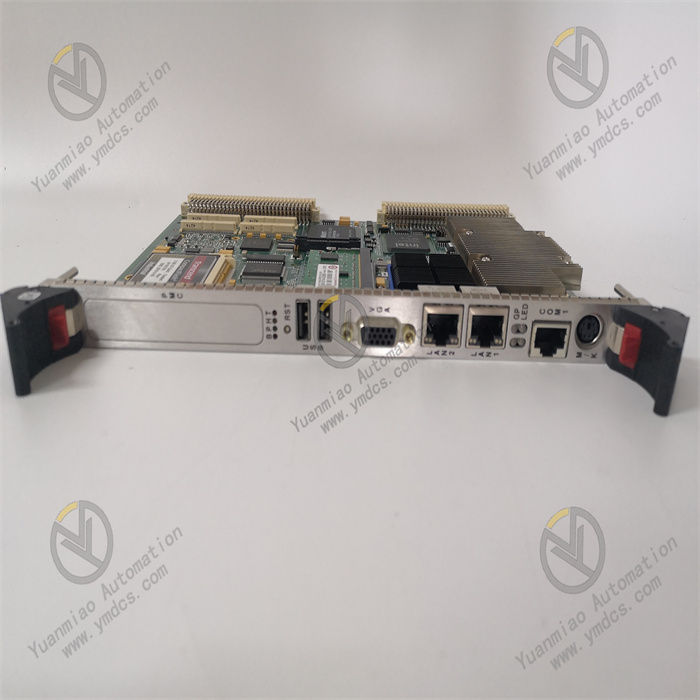
GE IS200PTURH1B
I. Overview
The GE IS200PTURH1B is a multi-functional core module developed specifically for the Mark VI gas turbine control system. It integrates the dual core capabilities of "turbine safety protection" and "AC high-current measurement and control", and plays a key role in monitoring the operating status of industrial equipment, providing abnormal early warnings, and conducting emergency interventions. Breaking the limitations of traditional single-function modules, it can not only provide safety protection such as overspeed and flame detection for rotating machinery like gas turbines and steam turbines, but also accurately measure and control AC high currents in industries such as electroplating and electrolysis. It is widely used in scenarios with strict requirements for reliability and measurement-control accuracy, including gas turbine control in power plants, integrated automation of substations, chemical electrolysis processes, and metallurgical electrical systems.
II. Technical Parameters
| Parameter Category | Specific Specifications | Remarks |
|---|---|---|
| Core Measurement & Control Parameters | Current Measurement Range: 0-5000A AC | Based on the Rogowski principle, no magnetic core saturation issue, suitable for high-current industrial scenarios |
| Current Measurement Accuracy: ±0.5% FS | Meets the high-precision current control requirements of electroplating, electrolysis, and other processes | |
| Response Time: ≤0.04 seconds | Quickly captures current fluctuations and equipment abnormalities to ensure timely triggering of protection mechanisms | |
| Turbine Protection Parameters | Speed Measurement Input: 4-channel passive magnetic pulse signals | Compatible with gear speed sensors, capable of detecting speed signals as low as 2RPM |
| Overspeed Trip Threshold: Configurable (typical value: 110%-115% of rated speed) | Uses median speed signal calculation to reduce single-point measurement errors | |
| Flame Detection Input: 8-channel Geiger-Mueller detector signals | Requires external 335V DC/0.5mA power supply, suitable for gas turbine flame monitoring | |
| Trip Output: 3-channel relay signals (for controlling emergency solenoid valves) | Cooperates with 9 magnetic relays on the TRPG terminal board, supporting TMR/simplex systems | |
| Power Supply & Communication | Operating Power Supply: 125V DC | Compatible with industrial safety power supply systems, ripple tolerance ≤10% |
| Communication Interface: VME bus | Interacts with the Mark VI system backplane to transmit measurement-control data and fault information | |
| Physical & Environmental Parameters | Installation Method: Standard VME single-slot installation | Suitable for 19-inch industrial control cabinets, with 3 status indicator LEDs on the panel |
| Operating Temperature: -30°C to 65°C, Storage Temperature: -40°C to 85°C | Wide-temperature design, suitable for extreme environments such as power plants and metallurgical plants | |
| Protection Rating: IP20 (module itself) | Works with cabinet protection to resist dust and splashes |
III. Core Functional Features
1. Unsaturated High-Current Measurement & Control Technology
2. Multiple Turbine Safety Protection Mechanisms
- Overspeed Protection: It collects turbine speed through 4-channel passive magnetic pulse inputs and processes the signals using a median filtering algorithm. When the speed exceeds the set threshold, 3-channel trip relays are triggered within 100ms to drive the emergency solenoid valves on the TRPG terminal board, realizing turbine shutdown.
- Flame Monitoring: It connects to 8-channel Geiger-Mueller flame detectors to real-time monitor the flame status in the gas turbine combustion chamber. When a flameout signal is detected, it immediately cuts off the fuel supply and triggers an alarm.
- Shaft Status Monitoring: It continuously measures the voltage and current induced by the turbine shaft. When an abnormal increase in shaft current is detected (indicating bearing wear), it sends early warning information to the upper computer to avoid severe equipment damage.
3. Highly Reliable Redundant Collaborative Control
4. Wide-Scenario Adaptability and System Compatibility
5. Full-Lifecycle Status Management
IV. Common Faults and Solutions
| Fault Phenomenon | Possible Causes | Solutions |
|---|---|---|
| 1. Current measurement value is 0, FAULT light is on | 1. Loose or broken connection of the Rogowski coil; 2. Loss of coil calibration parameters; 3. Fault of the internal signal processing chip | 1. Check the connection between the coil and the module terminals (usually a 4-pin aviation connector), re-plug and fasten it; 2. Re-import the calibration parameters through Proficy software (GE original calibration files are required); 3. Inspect the signal processing chip (e.g., ADI AD7606), and replace the module if it is faulty |
| 2. Turbine overspeed does not trigger a trip | 1. Broken speed input signal line; 2. Incorrect trip threshold setting; 3. Communication fault with the TRPG board; 4. Stuck relay contacts | 1. Use an oscilloscope to detect the 4-channel speed pulse signals and troubleshoot sensor or line faults; 2. Verify the trip threshold setting in the Mark VI system (must comply with the equipment manual requirements); 3. Check the VME bus connection line and restart the system to refresh communication; 4. Turn off the power, restart after 30 seconds, and replace the relay module if it still fails |
| 3. False alarm of flame detection | 1. Abnormal power supply to the detector (no 335V DC connection); 2. Detector affected by electromagnetic interference; 3. Module channel drift | 1. Measure the detector power output of the TRPG board to ensure 335V DC/0.5mA is normal; 2. Add a shield to the detector line, ground it, and keep it away from inverter cables; 3. Enter the module calibration interface to perform zero calibration for the flame detection channel |
| 4. Communication interruption, system displays "Module Offline" | 1. Poor contact of the VME bus slot; 2. Module power fault; 3. Bus address conflict | 1. Turn off the system power, re-plug the module to ensure good contact; 2. Measure the 125V DC power input and check if the fuse (usually 1A) is burned out; 3. Reset the module address via the backplane DIP switch to avoid conflicts with other components |
| 5. Module shuts down automatically due to overheating | 1. Poor cabinet ventilation, ambient temperature exceeds 65°C; 2. Dust accumulation on the module heat sink; 3. Fault of the internal power module | 1. Install cabinet cooling fans or industrial air conditioners to reduce the temperature to below 60°C; 2. Use compressed air (0.2MPa) to blow off dust on the heat sink; 3. Detect the output voltage of the internal DC-DC power module, and contact GE-authorized maintenance if there is an abnormality |