Description
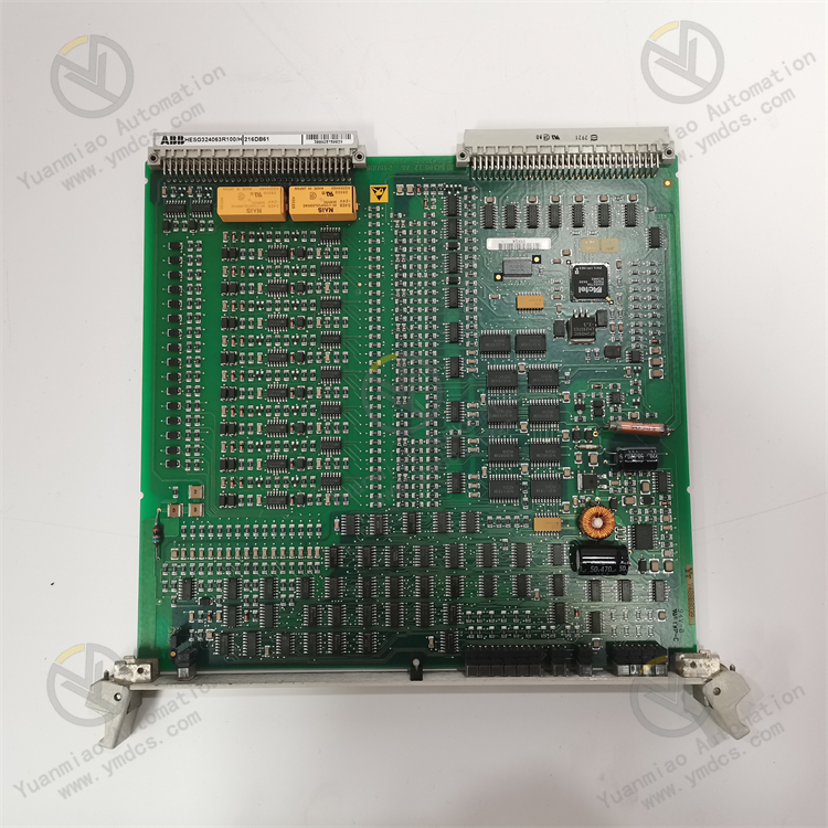
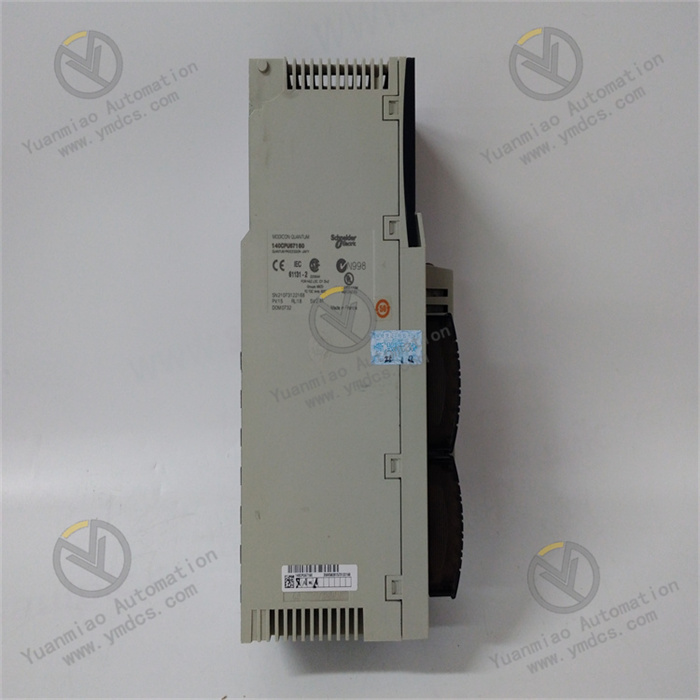
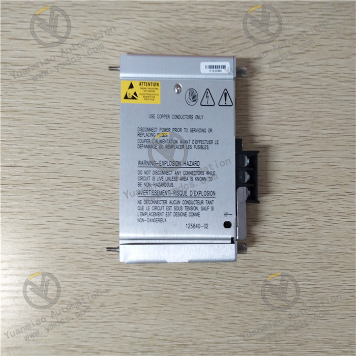
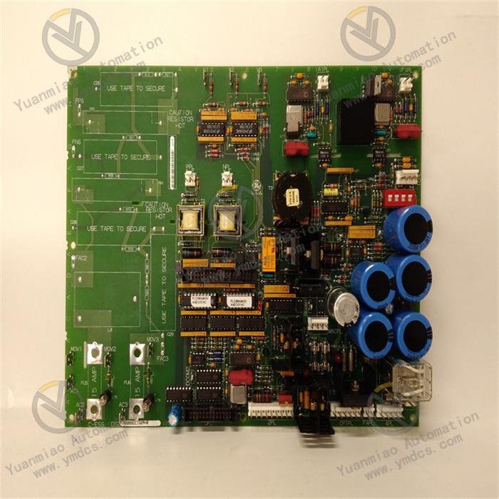
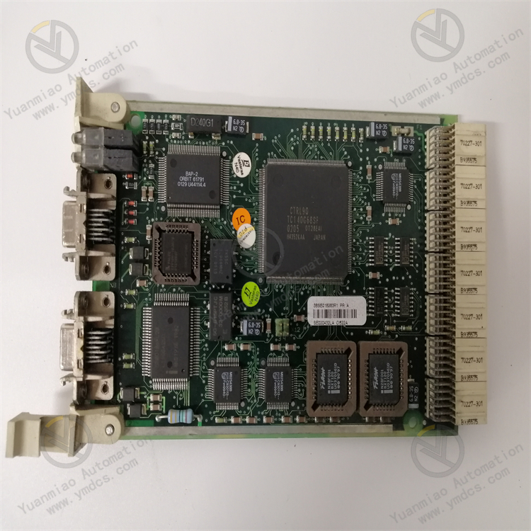
GE IS200STAOH2AAA
1. Overview
The GE IS200STAOH2AAA is an analog signal processing and output module developed for industrial gas turbine control systems. Its core positioning is a "precision control and analog signal conversion unit for gas turbine actuators", and it mainly serves industries such as power generation (e.g., F-class/H-class gas turbines in combined cycle power plants), petrochemicals (e.g., gas turbine-driven compressors in oil refineries), and energy (e.g., gas turbine waste heat power stations). It is a core signal interaction component in the GE Speedtronic Mark VIe gas turbine control system, connecting the controller with on-site actuators (such as fuel valves, guide vane actuators, and bypass valves).
2. Technical Specifications
2.1 Core Signal Processing Parameters
Analog Input (AI) Configuration
- Number of Channels: 8 independent differential analog input channels. Each channel can be independently configured with signal type, supporting "full activation of 8 channels" without performance degradation.
- Compatible Signal Types:
- Current signals: 4-20mA DC (input impedance 250Ω), 0-20mA DC (input impedance 250Ω);
- Voltage signals: 0-5V DC (input impedance 100kΩ), 0-10V DC (input impedance 100kΩ);
- Thermocouple signals: Type K (-270℃~+1372℃), Type J (-210℃~+1200℃), Type T (-270℃~+400℃);
- RTD signals: PT100 (3-wire, -200℃~+850℃, α=0.00385Ω/Ω/℃).
- Acquisition Precision:
- Current/voltage signals: ±0.05% F.S. (full scale);
- Thermocouple signals: ±0.1℃ (at 25℃), ±0.2℃ (outside the range of 25℃±100℃);
- RTD signals: ±0.05℃ (0℃~+200℃), ±0.1℃ (-200℃~0℃ / 200℃~+850℃).
- Sampling Rate: 1kHz per channel (configurable to 500Hz/200Hz/100Hz). The synchronization error of 8-channel simultaneous sampling is ≤ 5μs.
Analog Output (AO) Configuration
- Number of Channels: 8 independent analog output channels. Each channel can be independently configured with output type.
- Output Signal Types:
- Current output: 4-20mA DC (load ≤ 600Ω), 0-20mA DC (load ≤ 600Ω);
- Voltage output: 0-5V DC (load ≥ 10kΩ), 0-10V DC (load ≥ 10kΩ).
- Output Precision: ±0.1% F.S. (full scale), linearity ≤ ±0.02% F.S., output resolution 16-bit (65536 divisions).
- Response Time: ≤ 10ms (from receiving controller command to stable output), meeting the rapid adjustment requirements of actuators (e.g., millisecond-level opening adjustment of fuel valves).
2.2 Physical and Environmental Parameters
Physical Specifications
- Dimensions: 220mm (length) × 160mm (width) × 80mm (height) (including mounting clips). Adopting the standard rack slot design of the GE Mark VIe system, it can be directly inserted into the I/O rack of the Mark VIe control cabinet. It is dimensionally compatible with modules of the same series (e.g., IS200SAMBH1ABA, IS200SRTDH2ACB), allowing mixed installation in the cabinet to simplify layout.
- Weight: Approximately 1.2kg. The modular design supports insertion and removal by a single person, with a replacement time ≤ 5 minutes (equipped with quick-connect terminals).
- Terminals: Spring-loaded quick-connect terminals (compatible with 1.5mm²~2.5mm² wires) that require no screw fastening. This increases wiring efficiency by 50% and resists loosening due to vibration (contact resistance change ≤ 1mΩ in vibrating environments).
Environmental Adaptability
- Operating Temperature: -40℃~+70℃, meeting the operational requirements of high-temperature gas turbine rooms (up to 55℃ in poorly ventilated conditions in summer) and outdoor control cabinets in cold regions (-35℃ in winter). No preheating is required for low-temperature startup (-40℃), and the startup time is ≤ 20s.
- Humidity: 5%~95% (non-condensing, complying with IEC 60068-2-3 standard). In the high-humidity environment of coastal power plants, the circuit board shows no corrosion or leakage.
- Protection Rating: IP20 (for installation inside control cabinets), compatible with the overall IP54 protection system of the Mark VIe control cabinet, preventing dust from entering the module interior.
- Vibration and Shock Resistance: Vibration resistance rating of 10g (10Hz~2000Hz, complying with IEC 60068-2-6), capable of withstanding continuous vibration during gas turbine operation; shock resistance rating of 20g (11ms pulse, complying with IEC 60068-2-27), capable of withstanding shock loads during unit startup and shutdown.
- Electromagnetic Interference (EMI) Resistance: Complies with the EN 61000-6-2 industrial immunity standard. Electrostatic Discharge (ESD) protection: ±15kV (air discharge)/±8kV (contact discharge); radio frequency radiation immunity: 10V/m (80MHz~1GHz). In high-interference environments such as near generators and high-voltage cables, the output signal fluctuation is ≤ ±0.02% F.S.
2.3 Power Supply and Reliability Parameters
- Power Supply Requirements: Operating voltage: 24V DC (wide-range adaptation: 18V DC~36V DC), powered by the backplane of the Mark VIe system rack. Operating current ≤ 500mA (when 8 AI channels + 8 AO channels are fully activated), power consumption ≤ 12W, without increasing the power supply load of the cabinet.
- Isolation Performance: Three-level electrical isolation (input-output-power supply), with an isolation voltage ≥ 2500Vrms for 1 minute (input-ground, output-ground, input-output). Common Mode Rejection Ratio (CMRR) ≥ 100dB (50Hz), Differential Mode Rejection Ratio (DMRR) ≥ 80dB, effectively blocking ground loop interference and common-mode noise.
- Reliability Indicators: Mean Time Between Failures (MTBF) ≥ 350,000 hours (per Telcordia SR-332 standard at 25℃), design life ≥ 20 years. Key components (e.g., DAC chips, operational amplifiers) are selected from military-grade products, and the module supports "channel-level redundancy" (when a channel fails, backup channel parameter configuration can be activated).
- Communication Interface: Communicates with the Mark VIe controller (e.g., IC698CPE330) via the system backplane bus, with a data transmission rate of 100Mbps and latency ≤ 1ms. It supports channel parameter configuration, fault diagnosis, and data reading through the GE ControlST configuration software.
3. Functional Features
3.1 High-Precision Analog Signal Conversion and Output
- Low-Distortion Signal Conversion: Adopts 16-bit Δ-Σ ADC (input) and 16-bit DAC (output) chips, combined with "zero-temperature-drift" operational amplifiers (temperature coefficient ≤ 1ppm/℃). Within the operating temperature range of -40℃~+70℃, the signal conversion distortion is ≤ 0.01%. For example, when converting the controller's "50% fuel valve opening" command (corresponding to 12mA output) into an actuator signal, the actual output deviation is ≤ ±0.012mA, ensuring the fuel valve opening is accurately controlled within 50%±0.1% and avoiding unit power fluctuations caused by combustion instability.
Load Adaptive Adjustment: The AO channels are equipped with a "load impedance automatic detection" function. When the actuator load impedance changes within the range of 100Ω~600Ω (for current output) and 10kΩ~100kΩ (for voltage output), the module automatically adjusts the output driving capability to maintain constant output precision. For instance, when the load of the fuel valve actuator increases from 300Ω to 600Ω, the deviation of the 4-20mA output current remains ≤ ±0.02mA, ensuring control precision is not affected by load changes.
Multi-Signal Type Compatibility: The 8 AI channels can process four types of signals (current, voltage, thermocouple, and RTD) simultaneously without additional signal converters. For example, in gas turbine control, the AI channels can simultaneously collect: 4-20mA fuel pressure signals (0~3MPa), 0-10V guide vane position feedback signals (0%~100% opening), Type K thermocouple turbine exhaust temperature signals (600℃~1200℃), and PT100 bearing temperature signals (0℃~150℃), simplifying the system architecture and reducing integration costs.
3.2 Dedicated Control Optimization for Gas Turbine Actuators
- Actuator Control Mode Adaptation: Based on the characteristics of core gas turbine actuators, the module presets three dedicated modes: "Fuel Valve Control", "Guide Vane Control", and "Bypass Valve Control".
- Fuel Valve Control Mode: The output signal adopts a "slow start + fast adjustment" algorithm to avoid combustion chamber detonation caused by sudden increases or decreases in fuel supply (e.g., when the opening increases from 10% to 50%, the adjustment time is 1s, and the overshoot is ≤ 1%).
- Guide Vane Control Mode: Enables the "position feedback closed-loop" function. It collects the guide vane position feedback signal (0-10V) through the AI channel, compares it with the AO output command, and automatically corrects deviations (e.g., if the 12mA command corresponds to 50% opening but the feedback shows 49%, the output is automatically increased to 12.2mA), improving control precision to ±0.2%.
- Bypass Valve Control Mode: The output signal has a "fast shutdown" feature. When a unit fault occurs, the bypass valve output signal is switched from "closed" (4mA) to "fully open" (20mA) within 10ms to achieve rapid unloading and protect unit equipment.
In-Depth Collaboration with Protection Systems: The module communicates in real-time with the Safety Logic Unit (SLU) of the Mark VIe controller. When receiving an "emergency shutdown" command, the AO channels immediately cut off the output or switch to a safe value (e.g., the fuel valve output drops to 4mA, and the guide vane output drops to 4mA). The response time is ≤ 5ms, and the total time from fault trigger to safe actuator action is ≤ 50ms, avoiding major equipment damage.
- Historical Data Tracing: Supports uploading AI acquisition values and AO output values in the form of "timestamp + value" to the historical database (PHD) of the Mark VIe system via the controller. The storage cycle is configurable (10ms~1min). The ControlST software can be used to view trend curves (e.g., fuel valve output changes in the past 1 hour) and calculate adjustment frequencies (e.g., 3 adjustments per minute), providing data support for actuator fault diagnosis (e.g., frequent adjustments caused by jamming).
3.3 Industrial-Grade Reliability and Fault-Tolerant Design
- Extreme Environment Protection: The internal circuit board is coated with "nano-level three-proof paint + Teflon coating", providing triple protection against oil pollution, dust, and corrosion. In the high-oil-pollution environment of gas turbine rooms, the circuit board shows no oil accumulation or component corrosion after 5 years of continuous operation. The housing is made of magnesium-aluminum alloy (lightweight and with good thermal conductivity). When the module operating temperature reaches 70℃, the internal component temperature remains ≤ 85℃ (lower than the rated temperature of 125℃).
Channel-Level Fault Self-Diagnosis: Supports automatic diagnosis of 12 types of faults, including "AI channel open/short circuit", "AO channel overload/short circuit", and "DAC/ADC failure". When a channel fails, the module immediately displays a fault code on the system HMI (e.g., "E06 = AO3 Channel Overload") and records the fault occurrence time and signal data of the 10 seconds before the fault (e.g., AO output suddenly changes from 12mA to 0mA). This allows maintenance personnel to quickly locate the fault point (e.g., actuator short circuit), reducing troubleshooting time from 2 hours to 30 minutes.
Redundant Configuration Support: Supports "1:1 hot redundancy" configuration (main and standby modules operate in parallel). The main module synchronizes channel parameters, collected data, and output status to the standby module in real-time via the backplane bus. When the main module fails (e.g., power supply abnormality), the standby module automatically takes over the signal processing and output of all channels within 10ms without interrupting data interaction with the controller. This ensures "zero interruption" of actuator control and complies with the IEC 61508 SIL 2 safety level requirements (suitable for critical scenarios such as gas turbines supporting nuclear power plants).
3.4 Convenient Maintenance and Intelligent Functions
- Simplified ControlST Configuration: Through the GE ControlST software, parameters such as signal type, range, filtering level, and control mode for each AI/AO channel can be configured graphically. It supports the "parameter copy" function (copying the configuration of one channel to other channels), with the configuration time for 8 AI + 8 AO channels ≤ 15 minutes. It also supports "online parameter modification" (without shutdown), such as adjusting the adjustment speed of the fuel valve control mode according to seasonal changes.
Remote Diagnosis and Calibration: Remote maintenance of the module can be realized through the Ethernet interface of the Mark VIe system. Maintenance personnel can view the acquisition values, output values, and fault status of each channel in the central control room. It supports "remote calibration" (inputting a standard signal, e.g., 12mA input to the AI channel corresponding to 50% range, and 12mA calibration value output from the AO channel), and the module automatically corrects deviations. There is no need to disassemble the cabinet on-site, increasing calibration efficiency by 80%.
Health Status Monitoring: The module is equipped with a built-in "self-health monitoring" function, which continuously monitors the power supply voltage (24V DC ±10%), internal temperature (≤ 85℃), and bus communication status. When an abnormality occurs (e.g., internal temperature rises to 90℃), it issues a "module early warning" signal in advance (without affecting signal processing and output), reminding maintenance personnel to replace the module in a planned manner and avoiding unit shutdown caused by sudden faults.
4. Operation Guide
4.1 Installation Process
Preparation for Installation
- Module Inspection: After unpacking, check that the module has no deformation in appearance, no damage to terminals, the label model (IS200STAOH2AAA) is consistent with the order, and accessories (mounting clips, quick-connect terminals, manual) are complete.
- Tools and Materials: Prepare a Phillips screwdriver (PH2), wire stripper, crimping tool, insulation tester (2500V), and insulating gloves. Ensure that the I/O rack slot of the Mark VIe control cabinet is free (e.g., Slot 5).
- Environment Inspection: The control cabinet should be well-ventilated. A heat dissipation space of ≥ 50mm should be reserved around the module installation position. It should be kept away from high-interference equipment such as frequency converters and high-power contactors. The cabinet grounding resistance should be ≤ 4Ω.
Installation Steps
- Rack Power Off: Turn off the power supply of the I/O rack in the Mark VIe control cabinet. After verifying that there is no electricity, clean the pins in the rack slot (free of dust and oxidation).
- Module Insertion: Align the module with the rack slot (note that the positioning protrusion on the module matches the positioning groove of the slot), push it in slowly until a "click" sound is heard (indicating the mounting clip is locked), and gently shake the module to confirm it is not loose.
- **Wiring Operation (to be performed by certified high-voltage electricians