Description
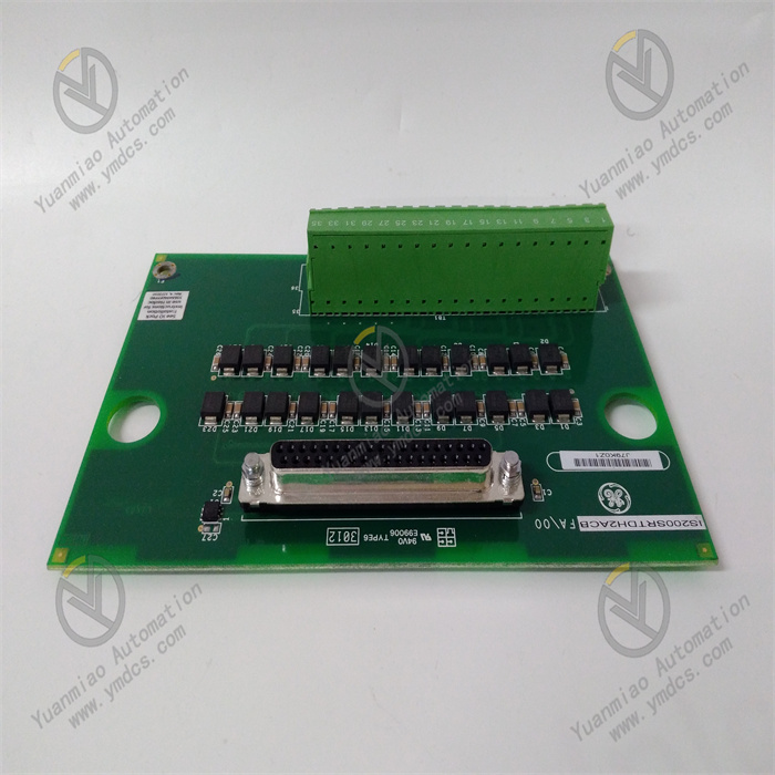
GE IS200SRTDH2ACB
1. Overview
The GE IS200SRTDH2ACB is a high-precision RTD (Resistance Temperature Detector) signal acquisition module developed specifically for industrial gas turbine control systems. Its core positioning is a "unit for accurate temperature parameter acquisition of key gas turbine components", and it mainly serves industries such as power generation (e.g., F-class/H-class gas turbines in combined cycle power plants), petrochemicals (e.g., gas turbine-driven compressors in oil refineries), and energy (e.g., gas turbine waste heat power stations). It is a core component in the GE Speedtronic Mark VIe gas turbine control system for temperature monitoring of key parts such as bearing temperature, stator winding temperature, and turbine cylinder temperature.
2. Technical Specifications
2.1 Core Signal Acquisition Parameters
RTD Channel Configuration
- Number of Channels: 16 independent differential RTD input channels. Each channel can be independently configured with RTD type and measurement range, supporting "full activation of 16 channels" without performance degradation (some similar modules experience reduced accuracy when multiple channels operate simultaneously).
- Compatible RTD Types: PT100 (resistance of 100Ω at 0℃, α = 0.00385Ω/Ω/℃), PT1000 (resistance of 1000Ω at 0℃, α = 0.00385Ω/Ω/℃). Supports 2-wire/3-wire/4-wire connection (3-wire/4-wire connection can eliminate the influence of lead resistance).
- Measurement Range: -200℃ to +850℃ (for PT100), -50℃ to +600℃ (for PT1000), covering the temperature ranges of various key gas turbine components (bearing temperature: 0℃ to +150℃; winding temperature: 0℃ to +200℃; turbine cylinder temperature: +200℃ to +600℃).
Acquisition Accuracy and Performance
- Measurement Accuracy: For PT100: ±0.05℃ within the range of 0℃ to +200℃, ±0.1℃ within the ranges of -200℃ to 0℃ and 200℃ to +850℃; for PT1000: ±0.1℃ within the range of 0℃ to +200℃, ±0.2℃ within the ranges of -50℃ to 0℃ and 200℃ to +600℃.
- Resolution: 0.01℃ (full range), capable of capturing tiny temperature changes (e.g., bearing temperature rising from 80.00℃ to 80.05℃).
- Sampling Rate: 1kHz per channel (configurable to 500Hz/200Hz/100Hz). The synchronization error of 16-channel simultaneous sampling is ≤ 5μs, ensuring the temporal consistency of temperature data from multiple components (e.g., simultaneous monitoring of temperature distribution across 8 bearings).
- Linearity: ≤ ±0.02% F.S. (full range), avoiding nonlinear distortion in the conversion between temperature and electrical signals.
2.2 Physical and Environmental Parameters
Physical Specifications
- Dimensions: 220mm (length) × 160mm (width) × 80mm (height) (including mounting clips). Adopting the standard rack slot design of the GE Mark VIe system, it can be directly inserted into the I/O rack of the Mark VIe control cabinet. It is dimensionally compatible with signal modules of the same series (e.g., IS200SAMBH1ABA), allowing mixed installation in the cabinet to simplify layout.
- Weight: Approximately 1.1kg. The modular design supports insertion and removal by a single person, with a replacement time ≤ 5 minutes (equipped with quick-connect terminals).
- Terminals: Spring-loaded quick-connect terminals (compatible with 1.5mm²~2.5mm² wires) that require no screw fastening. This increases wiring efficiency by 50% and resists loosening due to vibration (contact resistance change ≤ 1mΩ in vibrating environments).
Environmental Adaptability
- Operating Temperature: -40℃ to +70℃, meeting the operational requirements of high-temperature gas turbine rooms (up to 55℃ in poorly ventilated conditions in summer) and outdoor control cabinets in cold regions (-35℃ in winter). No preheating is required for low-temperature startup (-40℃), and the startup time is ≤ 20s.
- Humidity: 5% to 95% (non-condensing, complying with IEC 60068-2-3 standard). In the high-humidity environment of coastal power plants, the circuit board shows no corrosion or leakage.
- Protection Rating: IP20 (for installation inside control cabinets), compatible with the overall IP54 protection system of the Mark VIe control cabinet, preventing dust from entering the module interior.
- Vibration and Shock Resistance: Vibration resistance rating of 10g (10Hz~2000Hz, complying with IEC 60068-2-6), capable of withstanding continuous vibration during gas turbine operation; shock resistance rating of 20g (11ms pulse, complying with IEC 60068-2-27), capable of withstanding shock loads during unit startup and shutdown.
- Electromagnetic Interference (EMI) Resistance: Complies with the EN 61000-6-2 industrial immunity standard. Electrostatic Discharge (ESD) protection: ±15kV (air discharge)/±8kV (contact discharge); radio frequency radiation immunity: 10V/m (80MHz~1GHz). In high-interference environments such as near generators and high-voltage cables, the signal acquisition fluctuation is ≤ ±0.02℃.
2.3 Power Supply and Reliability Parameters
- Power Supply Requirements: Operating voltage: 24V DC (wide-range adaptation: 18V DC~36V DC), powered by the backplane of the Mark VIe system rack. Operating current ≤ 400mA (when 16 channels are fully activated), power consumption ≤ 9.6W, without increasing the power supply load of the cabinet.
- Isolation Performance: Three-level electrical isolation (input-output-power supply), with an isolation voltage ≥ 2500Vrms for 1 minute (input-ground, output-ground, input-output). Common Mode Rejection Ratio (CMRR) ≥ 100dB (50Hz), Differential Mode Rejection Ratio (DMRR) ≥ 80dB, effectively blocking ground loop interference and common-mode noise.
- Reliability Indicators: Mean Time Between Failures (MTBF) ≥ 400,000 hours (per Telcordia SR-332 standard at 25℃), design life ≥ 20 years. Key components (e.g., ADC chips, reference voltage sources) are selected from military-grade products, and the module supports a "redundant channel" design (when a channel fails, backup channel parameter configuration can be activated).
- Communication Interface: Communicates with the Mark VIe controller (e.g., IC698CPE330) via the system backplane bus, with a data transmission rate of 100Mbps and latency ≤ 1ms. It supports channel parameter configuration, fault diagnosis, and data reading through the GE ControlST configuration software.
3. Functional Features
3.1 Dedicated High-Precision RTD Signal Acquisition
- Lead Resistance Compensation Technology: To address errors caused by lead resistance in 2-wire RTD connections, the module is equipped with a built-in "automatic lead resistance compensation" algorithm. By measuring the lead loop resistance (≤ 5Ω), it automatically deducts the temperature deviation corresponding to the lead voltage drop from the acquired value (e.g., a 2Ω lead resistance corresponds to an approximate 5℃ error, which is reduced to ≤ ±0.05℃ after compensation). For 3-wire/4-wire connections, independent current/voltage measurement channels completely eliminate the influence of lead resistance, ensuring acquisition accuracy for long-distance wiring (≤ 100 meters).
Low-Temperature-Drift Acquisition Circuit: Adopts a 16-bit Δ-Σ ADC chip (sampling rate: 1kHz) and a "zero-temperature-drift" reference voltage source (temperature coefficient ≤ 1ppm/℃). Within the operating temperature range of -40℃ to +70℃, the reference voltage fluctuation is ≤ 0.1mV, corresponding to a temperature error ≤ 0.0025℃. For example, when the temperature of the gas turbine room rises from 25℃ to 55℃, the deviation of the bearing temperature (80℃) acquired by the module remains ≤ ±0.03℃, far exceeding that of ordinary modules (±0.1℃).
Multi-Channel Synchronous Sampling: The 16 channels share the same sampling clock, with a synchronous acquisition time error ≤ 5μs, enabling accurate analysis of the correlation between temperatures of various gas turbine components. For instance, by simultaneously monitoring the temperatures of the front, middle, and rear turbine cylinders (600℃, 500℃, and 400℃ respectively), abnormal thermal deformation of the cylinder can be detected in advance through changes in temperature gradient (e.g., the temperature difference between the front and rear cylinders decreasing from 200℃ to 180℃), preventing friction between rotating and stationary components (with a single fault loss exceeding RMB 2,000,000).
3.2 Dedicated Adaptation for Gas Turbine Temperature Monitoring
- Optimization for Key Component Monitoring: Based on the characteristics of different temperature monitoring points of gas turbines, the module can preset three acquisition parameter modes: "Bearing Mode", "Winding Mode", and "Cylinder Mode".
- Bearing Mode: Sampling rate of 500Hz, with the "vibration filtering" algorithm activated (to filter signal fluctuations caused by vibration), and temperature alarm thresholds set to 85℃ (early warning)/95℃ (shutdown).
- Winding Mode: Sampling rate of 1kHz, with the "fast response" mode activated (capturing sudden temperature rises within 10ms), and alarm thresholds set to 150℃ (early warning)/180℃ (shutdown).
- Cylinder Mode: Sampling rate of 200Hz, with "high-temperature linear compensation" activated (compensating for nonlinear errors above +600℃), and alarm thresholds set to 650℃ (early warning)/700℃ (shutdown).
In-Depth Collaboration with Protection Systems: The temperature data acquired by the module is transmitted in real-time to the Safety Logic Unit (SLU) of the Mark VIe controller via the backplane bus. When the temperature of a component reaches the alarm threshold (e.g., the bearing temperature rises to 95℃, the shutdown threshold), the module outputs an "emergency shutdown" trigger signal within 1ms (via DO linkage terminals). At the same time, the controller cuts off fuel supply and initiates the coast-down procedure. The response time from temperature exceeding the limit to safe unit shutdown is ≤ 500ms, preventing bearing burnout.
Historical Data and Trend Analysis: Supports uploading temperature data of each channel in the form of "timestamp + temperature value" to the historical database (PHD) of the Mark VIe system via the controller. The storage cycle is configurable (1s~1min). The ControlST software can be used to view temperature trend curves (e.g., 24-hour bearing temperature changes) and calculate temperature rise rates (e.g., 0.5℃ per minute), providing data support for preventive maintenance. For example, through the monthly trend of bearing temperature (slowly rising from 75℃ to 80℃), the aging of the lubrication system can be determined, and lubricating oil can be replaced in advance (costing approximately RMB 20,000), avoiding bearing scrapping (costing over RMB 500,000).
3.3 Industrial-Grade Reliability and Fault-Tolerant Design
- Extreme Environment Protection: The internal circuit board is coated with "nano-level three-proof paint + Teflon coating", providing triple protection against oil pollution, dust, and corrosion. In the high-oil-pollution environment of gas turbine rooms, the circuit board shows no oil accumulation or component corrosion after 5 years of continuous operation. The housing is made of magnesium-aluminum alloy (lightweight and with good thermal conductivity). When the module operating temperature reaches 70℃, the internal component temperature remains ≤ 85℃ (lower than the rated temperature of 125℃).
Channel-Level Fault Self-Diagnosis: Supports automatic diagnosis of 8 types of faults, including "channel open/short circuit", "RTD damage", and "ADC failure". When a channel fails, the module immediately displays a fault code on the system HMI (e.g., "E04 = Channel 5 RTD Open Circuit") and records the fault occurrence time and temperature data of the 10 seconds before the fault (e.g., a sudden change from 80℃ to "----"). This allows maintenance personnel to quickly locate the fault point (e.g., broken RTD cable), reducing troubleshooting time from 2 hours to 30 minutes.
Redundant Configuration Support: Supports "1:1 hot redundancy" configuration (main and standby modules operate in parallel). The main module synchronizes channel parameters and acquired data to the standby module in real-time via the backplane bus. When the main module fails (e.g., power supply abnormality), the standby module automatically takes over the acquisition and signal output of all channels within 10ms without interrupting data reception by the controller. This ensures "zero interruption" of gas turbine temperature monitoring and complies with the IEC 61508 SIL 2 safety level requirements (suitable for critical scenarios such as gas turbines supporting nuclear power plants).
3.4 Convenient Maintenance and Intelligent Functions
- Simplified ControlST Configuration: Through the GE ControlST software, parameters such as RTD type (PT100/PT1000), connection method (2/3/4-wire), sampling rate, and alarm threshold for each channel can be configured graphically. It supports the "parameter copy" function (copying the configuration of one channel to other channels), with the configuration time for 16 channels ≤ 10 minutes. It also supports "online parameter modification" (without shutdown), such as adjusting the bearing temperature early warning threshold according to seasonal changes (set to 80℃ in summer and 85℃ in winter).
Remote Diagnosis and Calibration: Remote maintenance of the module can be realized through the Ethernet interface of the Mark VIe system. Maintenance personnel can view the acquired values, fault status, and historical data of each channel in the central control room. It supports "remote calibration" (inputting a standard resistance signal, e.g., 138.5Ω corresponding to 100℃ for PT100), and the module automatically corrects deviations. There is no need to disassemble the cabinet on-site, increasing calibration efficiency by 80%.
Health Status Monitoring: The module is equipped with a built-in "self-health monitoring" function, which continuously monitors the power supply voltage (24V DC ±10%), internal temperature (≤ 85℃), and bus communication status. When an abnormality occurs (e.g., internal temperature rising to 90℃), it issues a "module early warning" signal in advance (without affecting temperature acquisition), reminding maintenance personnel to replace the module in a planned manner and avoiding sudden faults.
4. Installation Process
Preparation for Installation
- Module Inspection: After unpacking, check that the module has no deformation in appearance, no damage to terminals, the label model (IS200SRTDH2ACB) is consistent with the order, and accessories (mounting clips, quick-connect terminals, manual) are complete.
- Tools and Materials: Prepare a Phillips screwdriver (PH2), wire stripper, crimping tool, insulation tester (2500V), and insulating gloves. Ensure that the I/O rack slot of the Mark VIe control cabinet is free (e.g., Slot 4).
- Environment Inspection: The control cabinet should be well-ventilated. A heat dissipation space of ≥ 50mm should be reserved around the module installation position. It should be kept away from high-interference equipment such as frequency converters and high-power contactors. The cabinet grounding resistance should be ≤ 4Ω.
Installation Steps
- Rack Power Off: Turn off the power supply of the I/O rack in the Mark VIe control cabinet. After verifying that there is no electricity, clean the pins in the rack slot (free of dust and oxidation).
- Module Insertion: Align the module with the rack slot (note that the positioning protrusion on the module matches the positioning groove of the slot), push it in slowly until a "click" sound is heard (indicating the mounting clip is locked), and gently shake the module to confirm it is not loose.