Description
GE IS200DSPXH1DBD
I. Overview
The GE IS200DSPXH1DBD digital signal processor (DSP) control board is a core component of its Mark VI turbine control system series. This series of control systems is widely used in industrial gas turbine and steam turbine systems, playing a crucial role in the energy production sector. As a key part of this series, the IS200DSPXH1DBD is particularly suitable for Innovation series drives and Ex2100 exciters, undertaking complex data processing and precise control tasks.
To meet the industrial demand for efficient, intelligent, and stable turbine control, GE has continuously invested in research and development. It upgraded and optimized the original Mark V turbine control system and launched the Mark VI series. During this process, the IS200DSPXH1DBD emerged. It integrates advanced digital signal processing technology, high-performance hardware configuration, and flexible software algorithms, aiming to provide more reliable and precise control solutions for various turbine equipment. This helps industrial production improve efficiency, reduce energy consumption, and ensure safety.
This control board is mainly targeted at industries with extremely high requirements for energy supply stability and equipment operation reliability, such as the power industry, petrochemical industry, and metallurgical industry. Large-scale turbine equipment in these industries requires precise control and monitoring to ensure the continuity and stability of the production process. With its excellent performance and reliability, the IS200DSPXH1DBD occupies an important position in the market and has become the preferred accessory for many enterprises to ensure the stable operation of key equipment.
II. Technical Parameters
(I) Electrical Parameters
Power Supply Requirements
The control board requires a stable power supply to ensure normal operation. Typically, the input voltage is [specific voltage value], with an allowable voltage fluctuation range of ±[X]%. For example, if the input voltage is 24V DC, the fluctuation range may be ±5%, i.e., between 22.8V and 25.2V. A stable power supply voltage is the foundation for the reliable operation of the control board. If the voltage fluctuation exceeds this range, it may cause abnormal operation of the control board or even damage internal electronic components.
Operating Current
Under normal operating conditions, the operating current of the IS200DSPXH1DBD is [specific current value]. Different workloads and operating conditions may cause fluctuations in the operating current, but generally, it remains within the design allowable range. Understanding the operating current parameter is helpful for the reasonable configuration of the power supply system, ensuring that the power supply can provide sufficient power support for the control board while preventing power supply overload or control board overheating due to excessive current.
(II) Physical Parameters
Dimension Specifications
The external dimensions of the control board are [specific length × width × height dimensions]. Its compact overall design facilitates installation in the cabinets of various turbine control equipment. On the premise of not affecting its functional implementation, this compact dimension design maximizes the saving of installation space and improves equipment integration. In some industrial sites with limited space, such as the control cabinets of small power stations, the compact size of the control board allows for more convenient layout and installation, reducing the equipment footprint.
Weight
Its weight is [specific weight value], which is relatively light, facilitating transportation and installation operations. The light weight reduces the labor intensity during installation; meanwhile, during equipment maintenance and control board replacement, it also makes it easier for operators to perform disassembly and installation work, improving maintenance efficiency.
(III) Environmental Parameters
Operating Temperature Range
The IS200DSPXH1DBD can operate stably within a relatively wide temperature range, with an operating temperature range of [-X]℃ to [X]℃. For example, the control board can still operate normally in cold areas with a temperature of -20℃ or high-temperature industrial environments with a temperature of 50℃. This feature enables it to adapt to industrial application needs in different regions and under different working conditions. Whether in wind power generation equipment outdoors in northern winters or in petrochemical plants with high temperatures in southern summers, it can reliably perform control tasks.
Storage Temperature Range
During non-operating states such as equipment transportation and storage, its storage temperature range is [-X]℃ to [X]℃. Within this temperature range, the performance of the electronic components of the control board will not be significantly affected, ensuring that the equipment can still be put into normal use after long-term storage. Even if stored in an extreme temperature environment for a period of time, when the temperature returns to the operating temperature range, the control board can still operate stably, ensuring the long-term availability of the equipment.
Humidity Adaptability
It can adapt to an environment with a relative humidity of [X]% to [X]% (non-condensing). In high-humidity coastal areas or humid industrial workshop environments, the internal electronic components of the control board have undergone special treatment and possess good moisture-proof performance. This prevents faults such as short circuits and corrosion caused by humidity issues, ensuring the stable operation of the equipment under various humidity conditions.
(IV) Interface Parameters
Input/Output (I/O) Interfaces
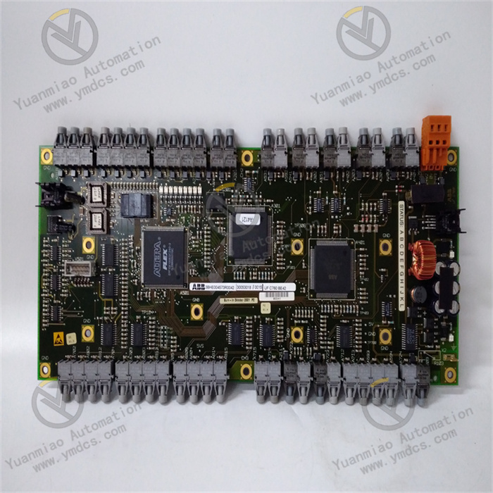
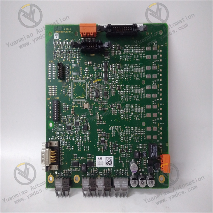
The control board is equipped with multiple input/output (I/O) interfaces, including two interfaces on the front panel and other hidden interfaces. These interfaces are used to connect various sensors, actuators, and other external equipment to realize data collection and control command output. Through the I/O interfaces, the control board can receive signals from temperature sensors, pressure sensors, speed sensors, etc., and send control signals to actuators such as motor drives and valve controllers, thereby achieving comprehensive monitoring and control of turbine equipment.
Backplane Interface Functions
Its right-angle backplane interface has multiple functions, including a data bus, address bus, control output signals, keyboard interface, tool interface, and VCO input. The data bus is responsible for transmitting data between various internal components of the control board and with external equipment; the address bus is used to determine the target address for data transmission; the control output signals are used to send control commands to external actuators to realize specific operations on the equipment; the keyboard interface can be connected to an operation keyboard, facilitating operators to perform parameter settings and equipment control; the tool interface can be used to connect professional debugging tools for equipment debugging, maintenance, and fault diagnosis; the VCO input interface is used to receive specific frequency signals to meet some special control requirements. These rich interface functions enable the IS200DSPXH1DBD to conduct efficient and stable communication and collaborative work with a variety of equipment, greatly expanding its application range and flexibility.
III. Functional Characteristics
(I) Powerful Data Processing Capability
High-Performance Digital Signal Processor
The IS200DSPXH1DBD is equipped with a high-performance digital signal processor (DSP) with an operating frequency of up to 60MHz. This powerful processor can quickly and accurately process large amounts of real-time data from sensors, such as parameters like turbine speed, temperature, and pressure. Taking a gas turbine as an example, during the unit's operation, sensors can collect thousands of sets of data per second. The DSP can analyze and calculate this data in an extremely short time, promptly determine the operating status of the unit, provide a reliable basis for subsequent control decisions, and ensure the stable operation of the gas turbine under various working conditions.
Efficient Logic and Calculation Functions
In addition to handling conventional data calculations, this control board also has strong logic processing capabilities. Through built-in algorithms, it can judge complex logical relationships. For example, during turbine startup, shutdown, and switching between different working conditions, it coordinates and controls the actions of various components in accordance with a preset logical sequence. When a steam turbine starts, the control board will start the oil pump, start the turning gear device, and gradually increase the steam intake in a specific logical sequence based on multiple conditions such as oil temperature, oil pressure, and steam pressure. This ensures a safe and smooth startup process and avoids equipment damage caused by improper startup.
(II) Precise Control Functions
Multi-Aspect Control Applications
In Innovation series drives, the IS200DSPXH1DBD serves as the main controller, providing precise control over the bridge circuit, motor regulator, and gating operations. It can flexibly adjust the output voltage, current, and frequency of the drive according to actual operation requirements, achieving precise control of motor speed and torque. In industrial production, for equipment such as fans and pumps that require precise speed control, the precise regulation of the drive by this control board allows the equipment to operate under optimal working conditions, improving energy utilization efficiency and reducing equipment wear.
Excitation Control Function
For the Ex2100 exciter, the control board undertakes the key function of generator magnetic field control. It can accurately adjust the excitation current according to the generator's operating status and load changes, maintaining the stability of the generator's output voltage. In the power system, when the grid load fluctuates, the IS200DSPXH1DBD can respond quickly and adjust the excitation current to ensure that the generator's output voltage is always maintained within the specified range. This guarantees the stability of power supply and reduces the impact of voltage fluctuations on the power grid and electrical equipment.
(III) Comprehensive Alarm and Indication Functions
LED Indicator Alarm
The front panel of the control board is equipped with two embedded LED indicators: one green and one red. The green indicator is usually used to display the normal operating status of the equipment; when all components of the equipment are working normally, the green light remains on. The red indicator is used for alarm indication. Once the control board detects an abnormality in equipment operation (such as faults like excessive turbine speed, excessively high temperature, or excessively low oil pressure), the red light will turn on immediately, reminding operators to take timely measures to prevent the fault from worsening. This intuitive alarm method allows operators to detect problems at the first time, improving the timeliness and accuracy of equipment maintenance.
Fault Information Storage and Query
In addition to the LED indicator alarm, the IS200DSPXH1DBD also has a fault information storage function. It stores various types of fault information that occur during equipment operation—including fault type, occurrence time, and equipment operating parameters at the time of the fault—in its internal memory. Operators can query these fault records using specialized tools or software to conduct in-depth analysis of the cause of the fault, formulate targeted maintenance plans, shorten equipment downtime, and improve equipment availability.