Description
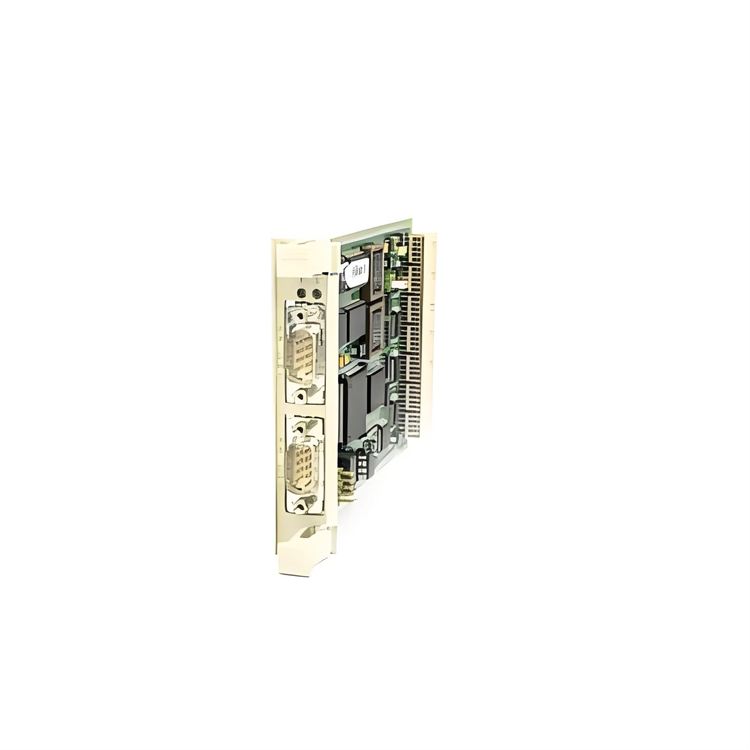
GE IC693DNM200-AB
I. Product Overview
GE IC693DNM200-AB, as a high-performance DeviceNet master control module, plays a crucial role in the field of industrial automation. It belongs to the GE Fanuc Series 90-30 PLC system and is a core component for building DeviceNet networks. With its excellent design and advanced technology, this module can efficiently connect and manage numerous devices on the DeviceNet network. Acting as a communication hub, it realizes stable and fast data exchange between devices as well as accurate transmission of control commands, providing a solid guarantee for the reliable operation of industrial automation systems. Whether it is complex production line control or process control scenarios with strict requirements on process parameters, IC693DNM200-AB can meet diverse industrial application needs with its powerful functions.
II. Technical Parameters
(I) Power Parameters
- Input Voltage: Supports 12-24 VDC power input. This relatively wide voltage range design enables it to adapt to various common industrial DC power supplies, enhancing its applicability in different power supply environments and ensuring stable power acquisition in various industrial sites.
- Inrush Current: An inrush current of 5.4A occurs at the moment of startup, but the duration is only 10 milliseconds. This characteristic indicates that the module can withstand a certain current impact during startup, and the short duration of the inrush current will not cause excessive adverse effects on the power supply system and the module itself, ensuring the stability and safety of the module startup process.
(II) I/O Parameters
- Output Point Configuration: It has 32 output points, which are cleverly organized into 4 groups, with 8 points in each group. This grouping design helps to carry out output control more efficiently. In practical applications, each group of output points can be set specifically according to different control requirements, improving the flexibility and convenience of output control.
- Output Current: Each output point can provide an output current of 0.5A, and the maximum current allowed by each group's common terminal is 3A. This output current parameter enables the module to easily drive various small load devices, meeting the needs of controlling low-power devices in industrial sites and ensuring that the output signal has sufficient driving capacity to stably control external devices.
(III) Communication Parameters
- Communication Rate: Fully supports 125K, 250K, and 500K baud rates specified by the DeviceNet standard. Users can flexibly choose the appropriate communication rate according to the different requirements for data transmission speed and distance in actual application scenarios. For example, in scenarios where high real-time data transmission is required and the distance between devices is short, the 500K baud rate can be selected to achieve high-speed data transmission; in cases where devices are scattered and the transmission distance is long, 125K or 250K baud rates can ensure the stability of data transmission while meeting long-distance communication needs.
- Maximum Number of Nodes: As the master station of the DeviceNet network, it can connect up to 63 slave devices. This strong connection capability makes it unnecessary to frequently add master station devices when building large-scale industrial automation networks, greatly simplifying the network architecture, reducing system costs, and improving the scalability and management efficiency of the entire network.
- Communication Protocol: Strictly follows the DeviceNet protocol standard to ensure seamless communication with other devices that meet this standard. In addition, it also has the ability to support multiple mainstream communication protocols such as Modbus TCP/IP and Profibus, which makes the module highly compatible in complex industrial automation systems, enabling data interaction with devices of different brands and types, effectively breaking down communication barriers between devices and providing convenience for building heterogeneous industrial networks.
(IV) Performance Parameters
- Response Time: The maximum switch response time is 0.5ms. Such a fast response speed enables the module to respond to changes in external signals in an extremely short time. In the industrial automation production process, the rapid monitoring and control of equipment status are crucial. The short response time characteristic of this module can effectively improve the real-time performance and control accuracy of the system, ensuring efficient and stable operation of the production process.
- Operating Environment: The operating temperature range is extremely wide, and it can work normally from -40°C to +85°C. The relative humidity can withstand 5%-95% (non-condensing) environmental conditions. This strong environmental adaptability enables it to operate stably in various harsh industrial environments, whether it is a high-temperature steel smelting workshop, a low-temperature cold storage environment, or a chemical production site with high humidity, IC693DNM200-AB can reliably complete data processing and communication tasks. At the same time, its protective design can effectively resist dust, foreign objects, and electromagnetic interference, further ensuring the normal operation of the module in complex industrial environments.
III. Functional Features
(I) Powerful Network Management Capability
As the master station of the DeviceNet network, IC693DNM200-AB is responsible for controlling and managing the entire network. It can systematically coordinate the data transmission and communication of up to 63 slave devices in the network, ensuring smooth information interaction between various devices. By reasonably allocating network resources and optimizing data transmission paths, the module can efficiently handle the data traffic generated by a large number of devices, avoid network congestion, and thus ensure the stable operation of the industrial automation system. For example, in an automobile manufacturing production line, numerous robots, sensors, actuators, and other devices are connected through the DeviceNet network, and IC693DNM200-AB can accurately manage the communication between these devices, making the entire production line operate efficiently and in coordination.
(II) Highly Flexible Configuration Method
The module allows users to configure flexibly through special software to meet diverse needs in different application scenarios. Users can freely set key configuration items such as the type of input and output signals, communication parameters, and device connection methods according to the actual industrial control logic. For example, in an industrial automation project involving various types of sensors and actuators, users can easily configure the corresponding parameters of IC693DNM200-AB in the software according to the characteristics of each device, making it perfectly compatible with various devices, greatly improving the efficiency and flexibility of system integration, and reducing the development cost and time consumption caused by inflexible hardware configuration.
(III) Excellent Communication Compatibility
In addition to standard support for the DeviceNet protocol, IC693DNM200-AB is also compatible with multiple mainstream communication protocols such as Modbus TCP/IP and Profibus. This feature enables it to have wide applicability in complex industrial automation ecosystems, allowing data interaction with devices of different brands and communication standards. In a large factory, there may be both old and new devices using different communication protocols. IC693DNM200-AB can integrate these devices into the same industrial network with its strong communication compatibility, realizing data sharing and collaborative control, avoiding the problem of device isolation caused by incompatible communication protocols, and providing strong support for enterprises to build a unified and efficient industrial automation network.
(IV) Reliable Diagnostic Function
The module has built-in comprehensive and powerful diagnostic tools that can monitor the health status of the network and connected devices in real-time. Through continuous monitoring and analysis of key information such as network communication status and device operating parameters, the diagnostic tools can promptly detect potential fault hazards and issue alarms to operators in an intuitive manner. For example, when a slave device in the network has communication interruptions, data transmission errors, or the device itself fails, the diagnostic function of IC693DNM200-AB can quickly locate the problem and provide detailed fault information, helping maintenance personnel quickly troubleshoot and repair, greatly reducing equipment downtime, improving the continuity and reliability of industrial production, and reducing economic losses caused by equipment failures.
(V) Excellent Industrial Adaptability
Exquisitely crafted with industrial-grade components, IC693DNM200-AB has high reliability and can cope with harsh industrial environments. Whether it is extreme climate conditions such as high temperature, low temperature, or high humidity, or complex industrial sites filled with electromagnetic interference and dust pollution, the module can operate stably, ensuring the smooth completion of data processing and communication tasks. Its excellent anti-interference ability effectively reduces the impact of external interference factors on the module's performance, ensuring the accuracy of data transmission and the reliability of control commands. In industries such as metallurgy and chemical industry that have high requirements for equipment stability, the excellent industrial adaptability of IC693DNM200-AB has been fully verified, playing an important role in ensuring the safety and stability of the production process.
IV. Operation Guide
(I) Installation Steps
- Preparation Before Installation: Before starting the installation, carefully inspect the appearance of the module to ensure there is no physical damage, such as cracked casing, bent or missing pins, etc. Carefully count the attached installation accessories, including but not limited to fixing screws, mounting brackets, communication cables, etc., to ensure all accessories are complete. At the same time, thoroughly clean the installation location to ensure the interior of the control cabinet is clean and tidy, free of dust and debris accumulation, and the temperature, humidity, and other conditions of the installation environment meet the specified operating range of the module. Be sure to cut off all power supplies related to the installation and strictly follow safety operating procedures, wearing insulating gloves, goggles, and other protective equipment to prevent electric shock, mechanical injury, and other safety accidents during installation.
- Module Fixing: Accurately place the IC693DNM200-AB module on the pre-selected standard rack installation position, ensuring the module is closely attached to the rack without any looseness or deviation. Use the matching fixing screws or special mounting brackets to firmly fix the module on the rack according to the specified torque requirements. When tightening the screws, pay attention to even force to avoid damaging the module due to excessive force or causing looseness during equipment operation due to insufficient fixing, which may lead to poor contact, abnormal signal transmission, and other problems affecting the normal operation of the module.
- Cable Connection: Strictly follow the wiring diagram provided by the module to connect the power cables, communication cables, and input/output signal lines in an orderly manner. During the connection process, be sure to carefully distinguish the positive and negative polarity of the cables and the functional definitions of each interface, ensuring each cable is connected firmly and in good contact, and eliminating connection errors such as short circuits, open circuits, and virtual connections. For power cables, select cables with appropriate wire diameters to ensure they can carry the current required for the normal operation of the module; for communication cables, select cables with corresponding transmission characteristics according to the adopted communication protocol and transmission distance, and pay attention to shielding measures to reduce signal interference and ensure communication stability and reliability; for input/output signal lines, select appropriate cable specifications according to the signal type of the connected equipment and conduct reasonable wiring to avoid cross-interference between signal lines and power lines. After the connection is completed, conduct a comprehensive and detailed inspection of all cable connections again, and only proceed to the next step after confirming they are correct.
(II) Programming and Configuration Process
- Software Installation: Install the programming and configuration software specially developed by GE for the IC693DNM200-AB module (such as [specific software name]). During the installation process, strictly follow the prompts of the software installation wizard to operate step by step, ensuring each installation step is accurate. At the same time, pay attention to installing relevant drivers to enable the computer to establish a stable and reliable communication connection with the module. After installation, perform necessary initial settings on the software, such as selecting the language, setting the working directory, configuring user permissions, etc., to build a good software environment for subsequent programming and configuration work.
- Communication Connection Establishment: Use a dedicated programming cable or network connection method to connect the communication interface of the computer to the programming interface of the IC693DNM200-AB module. After the connection is successful, open the programming and configuration software, and accurately set the parameters related to communication with the module in the software's communication settings interface, including but not limited to baud rate, IP address, subnet mask, gateway, etc. Ensure these parameters match the actual hardware configuration and network environment of the module to establish a stable and efficient communication link between the computer and the module. When setting communication parameters, carefully check each parameter value to avoid communication failure caused by incorrect parameter settings, which may affect the smooth progress of programming and configuration work.
- Parameter Configuration and Programming: According to the actual industrial automation control needs, flexibly use various configuration tools and programming languages in the programming and configuration software to perform detailed parameter configuration and control program writing for the IC693DNM200-AB module. The software provides a variety of functional instructions, library functions, and intuitive graphical configuration interfaces. Users can choose appropriate methods for configuration and programming according to specific application scenarios. For example, set the network topology, slave device parameters, input/output mapping relationships through the graphical interface; use ladder diagrams, instruction lists, and other programming languages to write complex control logic to achieve precise control of industrial equipment. When performing parameter configuration and programming, follow the structured and modular design principles to make the configuration files and control programs have a clear structure, easy to understand and maintain. At the same time, fully consider various possible abnormal situations and write corresponding error handling programs to improve the reliability and stability of the system.
- Configuration and Program Download: After completing the parameter configuration and control program writing, use the compilation and verification functions of the programming and configuration software to conduct a comprehensive check on the configurations made and the written programs. The software will automatically detect possible syntax errors, logical errors, and parameter conflicts, and give detailed error prompt information. According to the prompt information, carefully troubleshoot and correct errors until the compilation passes and the verification is correct. On the premise of ensuring stable communication between the computer and the module, download the compiled and verified configuration files and control programs to the IC693DNM200-AB module. During the download process, pay close attention to the download progress prompt to avoid download failure caused by unexpected situations such as communication interruptions and power failures. After the download is completed, use the online monitoring function of the software to view the operating status of the module, parameter settings, and the execution of the control program in real-time, and further debug and optimize the configuration and program to better meet the actual industrial control needs.
(III) Operation and Maintenance Points
- Startup and Operation Inspection: After completing the installation, programming configuration, and all connections of the module, turn on the module power. At this time, closely observe the status of the indicator lights on the module. Under normal circumstances, the power indicator should remain on, indicating that the module has been successfully connected to the power supply and the power supply is normal; the running indicator should flash according to a specific pattern, indicating that the module is in normal working condition. At the same time, through the programming and configuration software or the upper computer monitoring system, view the various operating parameters of the module in real-time, such as input/output signal status, communication status, equipment temperature, etc., to further confirm that the module is operating normally without any abnormalities. If the indicator light status is abnormal or the operating parameters exceed the normal range, stop the module operation immediately and carefully check the cause of the fault to avoid further expansion of the fault.
- Daily Maintenance: Conduct comprehensive maintenance inspections on the IC693DNM200-AB module regularly. Focus on checking whether the installation of the module is still firm and whether the wiring parts have signs of looseness, aging, or oxidation. Keep the environment around the module clean, ensure good ventilation, and avoid adverse effects on the module performance caused by high temperature, humid environment, and dust accumulation. Regularly view the running log of the module with the help of programming and configuration software, timely find potential problems from it, such as abnormal communication records and abnormal fluctuations of equipment operating parameters, and take corresponding measures in advance to ensure the long-term stable operation of the module. In addition, functional tests should be conducted on the module regularly to verify that all its functions are normal, such as communication functions, input/output functions, diagnostic functions, etc., ensuring the module always maintains a good working state in the entire industrial automation system.
- Fault Handling: If the IC693DNM200-AB module fails during operation, first carefully observe the blinking pattern of the indicator lights on the module, as different indicator light states often correspond to different fault types. At the same time, make full use of the fault diagnosis function of the programming and configuration software, combined with the indicator light prompts, to accurately determine the fault type. For example, if a communication fault occurs, focus on checking whether the communication parameter settings are correct, whether the communication line connections are firm, and check whether the communication cable is damaged, short-circuited, or open-circuited; if the input/output is abnormal, check whether the relevant wiring is loose and whether the externally connected equipment is working normally, such as whether the sensor is damaged or the actuator is faulty. After determining the cause of the fault, take targeted repair measures, such as resetting parameters, tightening wiring, replacing damaged equipment or components, etc. After troubleshooting, restart the module and conduct a comprehensive test on the system to ensure the module returns to normal operation and the entire industrial automation system can work stably and reliably.