Description
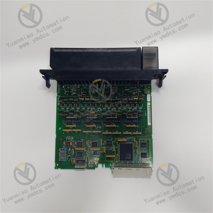
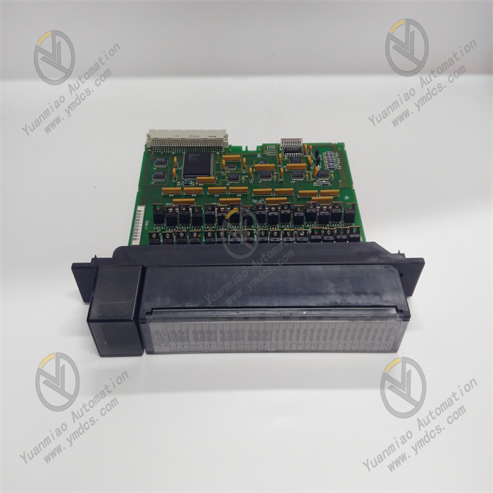
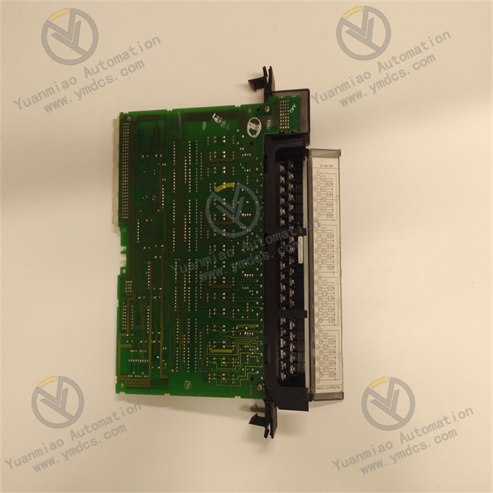
GE IC697MDL750
I. Product Overview
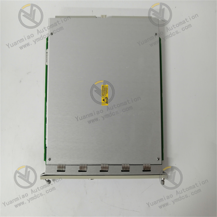
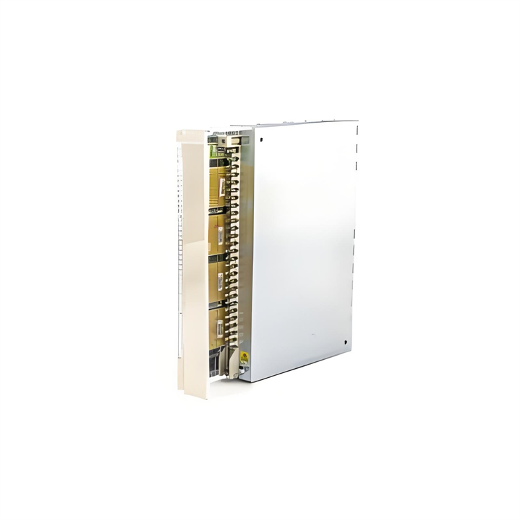
GE IC697MDL750 is a high-performance discrete output module belonging to the GE Fanuc Series 90-70 PLC system, playing an important role in the field of industrial automation control. This module is mainly responsible for converting the control commands issued by the PLC Central Processing Unit (CPU) into corresponding discrete output signals to drive external actuators, such as contactors, solenoid valves, indicator lights and other industrial equipment, so as to realize precise control of various equipment in the industrial production process. It has a compact design and adopts a standard rack mounting method, which can be seamlessly compatible with other modules in the Series 90-70 system to build a stable and efficient industrial automation control system. It is widely used in production line control and equipment linkage in industries such as automobile manufacturing, metallurgy, chemical industry, and electric power, providing reliable output control support for the automated operation of industrial production.
II. Technical Parameters
- Number of Output Points and Type: It has 16 discrete output points, and the output type is relay output. Relay output has strong load capacity and isolation performance, and can adapt to different types of loads, whether AC loads or DC loads can be driven, with strong compatibility, meeting the diverse equipment control needs of industrial sites.
- Rated Load Voltage: It supports AC load voltage ranges of 120V AC and 240V AC, and DC load voltage range of 24V DC. It can be flexibly selected according to the power supply requirements of actual industrial equipment, without the need for additional conversion equipment, simplifying the wiring and configuration of the system.
- Maximum Load Current: The maximum load current of each output point is 2A, and the total load current of a single module does not exceed 10A. This parameter ensures that the module can stably drive various conventional industrial actuators, and at the same time avoids damage to the module due to excessive load, ensuring the safe operation of the system.
- Electrical Isolation: It adopts an inter-channel electrical isolation design, with an isolation voltage of 250V AC, which can effectively prevent interference between different output channels, ensuring the independence and stability of each output signal. Especially in industrial sites where multiple devices work simultaneously and the electromagnetic environment is complex, it can significantly improve the anti-interference ability of the system.
- Response Time: The maximum turn-on response time of the output signal is 10ms, and the maximum turn-off response time is 5ms. The fast response speed ensures that control commands can be transmitted to the actuator in a timely manner, ensuring the real-time and accuracy of the industrial control process, and is suitable for scenarios with certain requirements for control precision.
- Working Environment: The operating temperature range is 0-60°C, and it can work stably in common temperature environments of industrial sites; the relative humidity is 5%-95% (non-condensing), and it can adapt to humid industrial environments, such as food processing workshops and water treatment plants; the storage temperature range is -40-85°C, which is convenient for the transportation and storage of the equipment.
- Installation Parameters: It adopts a standard 16-bit Series 90-70 rack mounting, with a module width of 3.5 inches (88.9mm), which conforms to the installation specifications of the system. It can be compactly arranged with other modules, saving installation space in the control cabinet and facilitating system integration and maintenance.
III. Functional Features
- Reliable Output Control Capability: GE IC697MDL750 adopts relay output mode, which has strong load driving capability and can stably drive various industrial actuators such as contactors and solenoid valves. The isolation characteristic of relay output realizes electrical isolation between the module and external loads, effectively protecting the PLC system from external voltage fluctuations and interference, improving the reliability of system operation, and reducing damage to the PLC system caused by external equipment failures.
- Flexible Load Adaptability: It supports multiple load voltages such as AC 120V, 240V and DC 24V, and can adapt to industrial equipment of different power supply types. There is no need to configure separate output modules for loads of different voltages, reducing system complexity and cost. In industrial sites, loads can be directly connected according to the actual power supply situation of the equipment, simplifying system design and wiring.
- Good Anti-Interference Performance: The inter-channel electrical isolation design and the overall anti-electromagnetic interference capability of the module enable IC697MDL750 to work stably in complex industrial electromagnetic environments. Even when multiple devices are running simultaneously and there is strong electromagnetic radiation, the module can accurately output control signals, avoiding misoperation and ensuring the stability of the industrial control process.
- Intuitive Status Indication: The module is equipped with LED status indicators corresponding to each output point. When the output point is in the on state, the corresponding indicator light is on; when it is in the off state, the indicator light is off. Operators can intuitively understand the working status of each output point through the status of the indicator lights, which is convenient for system debugging, fault troubleshooting and daily maintenance, and improves the maintainability of the system.
- Compact Structure Design: The module adopts a compact shape design, which conforms to the standardized size of the Series 90-70 system. It can be closely installed with other modules on the rack, saving space in the control cabinet. This compact design not only facilitates system integration but also makes the wiring between modules more concise, reducing the incidence of line faults.
- High Compatibility with the System: As part of the Series 90-70 PLC system, IC697MDL750 has good compatibility with other components in the system, such as CPU modules and input modules, and can work seamlessly. The module communicates with the CPU through the system backplane to ensure the rapid transmission and execution of control commands, facilitating the construction of a complete industrial automation control system.
IV. Operation Guide
Installation Steps
- Preparation Before Installation: First, check whether the appearance of the module is intact, whether there is damage, deformation, pin bending, etc., to ensure that the module has no physical damage. Prepare the required installation tools, such as screwdrivers, wire strippers, etc., as well as supporting installation accessories such as racks and screws. Confirm that the installation environment meets the working conditions of the module, such as temperature and humidity within the specified range, away from strong electromagnetic interference sources and corrosive gases.
- Module Installation: Install the Series 90-70 rack in a suitable position in the control cabinet to ensure that the rack is firmly fixed. Turn off the rack power supply, smoothly push the IC697MDL750 module into the selected slot along the rack guide rail until the module is fully inserted and in good contact with the rack backplane. Fix the front panel of the module on the rack with screws to ensure that the module is firmly installed and prevent loosening due to vibration during equipment operation.
- Wiring Connection: Refer to the module wiring diagram to connect the cables of external loads to the output terminals of the module. When wiring, pay attention to distinguishing the positive and negative poles of the load (DC load) or the phase line and neutral line (AC load) to ensure correct wiring. Each output point corresponds to an independent terminal, and connect them one-to-one according to the output point number and load to avoid wrong connection. After the connection is completed, gently pull the cable to check whether the wiring is firm to prevent virtual connection. After wiring, arrange the cables neatly to avoid messy cables affecting heat dissipation and subsequent maintenance.
Configuration and Debugging
- System Configuration: Create a project in GE Fanuc programming software (such as VersaPro), select the corresponding PLC model and IC697MDL750 module, and perform hardware configuration. According to the actual control requirements, set the output point address and related parameters of the module to ensure that the software configuration is consistent with the hardware connection. After the configuration is completed, download the project to the CPU of the PLC so that the CPU can correctly identify and control the output module.
- Output Test: Turn on the rack power supply, force the output point to be on or off through the programming software, observe whether the corresponding LED indicator on the module lights up or goes off normally, and check whether the external load acts according to the command. If it is found that the status of the indicator light is inconsistent with the output command or the load does not act, immediately turn off the power supply, check whether the wiring is correct, the load is normal, and the module is installed in place, etc., and retest after troubleshooting.
- Linkage Debugging: Connect the module to the entire industrial control system for linkage debugging. By running the control program, observe the output of the module under actual working conditions, verify that the output signal can accurately and timely drive the load, and ensure that the system operates normally according to the preset logic. During the debugging process, record the working status and related parameters of the module for subsequent analysis and optimization.
Operation and Maintenance
- Daily Operation Monitoring: During the operation of the system, regularly observe the status of the LED indicators on the module to confirm whether the working status of each output point is normal. Through programming software or upper computer monitoring system, monitor the output status and related data of the module in real-time to find abnormal situations in time. Pay attention to the working environment temperature and humidity of the module to ensure they are within the specified range, avoiding the impact of environmental factors on the module performance.
- Regular Maintenance: Clean the module regularly, wipe the dust on the surface of the module with a dry soft cloth to prevent dust accumulation from affecting heat dissipation. Check whether the installation screws of the module are loose, and whether the wiring terminals are oxidized or loose, and handle them in time if any. Check the external load to ensure that the load works normally, avoiding damage to the module due to load failure. Regularly test the output performance of the module, such as measuring output voltage, current and other parameters to ensure they meet the specified requirements.
- Troubleshooting: If the module has no output from the output point, first check whether the LED indicator corresponding to the output point is on. If the indicator is not on, it may be that the control program has not issued a command or there is a communication failure between the module and the CPU. Check the program and communication link; if the indicator is on, check whether the wiring is loose, the load is damaged, and the output terminal is in poor contact, etc. If the module itself is suspected to be faulty, replace it with a spare module for testing. After confirming the fault, send the faulty module for repair or replace it.


