Description
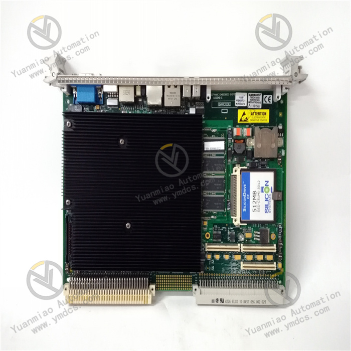
GE IC697CPX928-FE
I. Product Overview
GE IC697CPX928 - FE, as a high-performance Central Processing Unit (CPU) module, holds an important position in the field of industrial automation and belongs to the GE Fanuc Series 90 - 70 PLC system. This module is specially designed to meet complex industrial control needs and can perform precise real-time control over various machines, process flows, and material handling systems. Its compact single-slot design not only saves space but also facilitates collaboration with other modules. Through the rack-mounted backplane, it achieves efficient communication with I/O and intelligent option modules in the VME C.1 standard format, building a powerful industrial automation control network. It is widely used in multiple industries such as manufacturing, energy, and transportation, providing a solid guarantee for the efficient and stable operation of industrial production.
II. Technical Parameters
- Processor Performance: Equipped with a 96MHz 80486 DX4 microprocessor, it has strong data processing capability. The execution time of each Boolean function is only 0.4 microseconds, which can quickly process a large number of control instructions and data, ensuring timely system response and meeting the strict requirements for real-time performance in industrial automation scenarios. Whether it is complex logical operations or rapid processing of a large amount of I/O data, this processor can easily handle them, ensuring the smoothness and efficiency of the industrial control process.
- Memory Configuration: It provides 6MB of battery-backed memory, which can ensure that key data and programs in the memory are not lost in case of unexpected power outages, maintaining the continuity of the system's operating state. At the same time, it has 256K of non-volatile user flash memory for storing important user programs and configuration information, without the need for additional storage devices. This not only improves the stability of data storage but also facilitates users' management and update of programs.
- I/O Parameters: It supports up to 12K input and output points, and the types of input and output can be arbitrarily combined, which can adapt to the connection needs of various complex industrial on-site equipment. In addition, it has an analog I/O processing capability of up to 8K, which can accurately collect and control analog signals, such as temperature, pressure, flow, and other continuously changing physical quantities, providing strong support for the industrial automation system to achieve refined control.
- Communication Parameters: It is equipped with three serial ports, two of which are RS - 485 ports and one is an RS - 232 port. These ports can be used to connect programming devices, other intelligent devices, or perform data transmission, realizing convenient communication between the module and external devices. By flexibly setting communication parameters, it can meet different communication distance and rate requirements, ensuring stable and reliable data transmission. If necessary, an Ethernet module can be installed to realize Ethernet-based communication function, supporting the TCP/IP protocol, facilitating high-speed and large-data-volume communication with upper computers and monitoring systems, and making it easy to build large-scale industrial automation networks for remote monitoring and management.
- Power Parameters: The nominal current required for normal operation is 3.1 amperes, and the input voltage is 5 volts DC. In terms of heat dissipation, when the ambient temperature reaches 50 degrees Celsius (122 degrees Fahrenheit), a fan with an air volume of 70 cubic feet per minute (CFM) is required for forced air cooling to ensure the module can operate stably in high-temperature environments and prevent performance degradation or failures caused by overheating. Without forced air cooling, its operating temperature range drops to between 32 and 122 degrees Fahrenheit. At the same time, depending on the actual power supply type, a rack fan assembly powered by 120V AC, 240V AC, or 24V DC can be installed on the module to meet the heat dissipation needs in different application scenarios.
III. Functional Features
- Powerful Processing Capability: With a high-performance microprocessor and fast Boolean function execution speed, IC697CPX928 - FE can efficiently execute various complex control algorithms and logical operations, precisely control the operation of industrial equipment. It is suitable for industrial automation scenarios with high requirements for control accuracy and response speed, such as precision manufacturing production lines and automated logistics sorting systems, ensuring the accuracy and efficiency of the production process.
- Flexible Communication Compatibility: The rich serial port configuration and extended support for Ethernet communication enable it to communicate seamlessly with a variety of devices. It can not only work with I/O modules and intelligent option modules of the same series but also realize data interaction with devices of other brands through standard communication protocols, breaking down communication barriers between devices. In an industrial automation system containing multiple devices of different brands, this module can serve as a communication hub, integrating data from all parties to realize collaborative control and management of the entire system.
- Reliable Diagnostic Function: It has a built-in comprehensive self-diagnostic mechanism, which can monitor the operating status of the module itself and connected devices in real-time. Through continuous monitoring and analysis of key parameters, once an abnormality is found, such as communication failure or equipment failure, it can quickly locate the problem, issue an alarm to the operator intuitively through the seven status LEDs on the module, and generate detailed fault logs at the same time. This greatly shortens the fault troubleshooting time, improves the maintainability of the system, reduces the risk of production interruption caused by equipment failure, and ensures the continuity of industrial production.
- High Flexibility and Scalability: Adopting the modular design concept, users can flexibly select and match various optional modules according to actual industrial control needs, such as Ethernet interface modules, programmable coprocessors, alphanumeric coprocessors, bus controllers, communication modules, I/O link interfaces, and the entire IC697 discrete and analog I/O module series, etc., to easily expand the functions of the module and meet the needs of industrial automation projects of different scales and complexities. Whether it is the upgrading and transformation of small automated production lines or the new construction of large industrial control systems, this module can adapt to diverse application scenarios through flexible configuration.
- Data Storage and Protection: Large-capacity battery-backed memory and non-volatile user flash memory provide reliable guarantees for data storage. Important control programs, historical data, and equipment configuration information can be safely stored in the module, and data will not be lost even in case of sudden power outages or system failures. At the same time, through setting passwords and key switches, digital and physical double protection can be provided for equipment configuration to prevent unauthorized access and modification, ensuring the security and integrity of system data.
IV. Operation Guide
Installation Steps
- Preparation Before Installation: Before installation, ensure that the rack power supply is turned off, the operation control switch is set to the stop position, and the memory protection key switch is in the off position. Carefully inspect the appearance of the module to ensure there is no physical damage, such as cracked housing, bent or missing pins. Prepare the CMOS battery, confirm that the temperature, humidity, and other conditions of the installation environment meet the specified operating range of the module, and clean the installation location to ensure no dust or debris accumulation.
- Module Installation: Insert the CMOS battery into any of the battery connection slots. Carefully insert the IC697CPX928 - FE module into the pre-selected standard rack slot, ensuring that the module is closely fitted with the slot without any looseness or deviation. During the installation process, avoid excessive force or collision to prevent damage to the module.
- Cable Connection: According to actual application needs, use appropriate cables to connect the serial ports, Ethernet interface (if an Ethernet module is installed), and other related interfaces of the module. When connecting, strictly follow the wiring diagram, carefully distinguish the positive and negative polarity of the cables and the functional definitions of each interface, ensure that each cable is connected firmly and in good contact, and eliminate connection errors such as short circuits, open circuits, and virtual connections. After the connection is completed, conduct a comprehensive and detailed inspection of all cable connections again, and only proceed to the next step after confirmation.
- Power On: After completing all the above installation steps and checking that they are correct, turn on the rack power supply. At this time, closely observe the status of the indicator lights on the module. Under normal circumstances, the power indicator should remain on, indicating that the module has been successfully connected to the power supply and the power supply is normal; other status LEDs should flash according to a specific pattern, indicating that the module is in a normal working state. If the indicator light status is abnormal, stop the operation immediately and carefully check the cause of the fault to avoid further expansion of the fault.
Programming and Configuration Process
- Software Installation: Install the programming and configuration software suitable for the IC697CPX928 - FE module, which is usually provided by GE and can run on MS - DOS system, Windows 95, or Windows NT system. During the installation process, strictly follow the prompts of the software installation wizard to operate step by step, ensuring that each installation step is accurate. At the same time, pay attention to installing relevant drivers to enable the computer to establish a stable and reliable communication connection with the module. After installation, perform necessary initialization settings on the software, such as selecting the language, setting the working directory, and configuring user permissions, to build a good software environment for subsequent programming and configuration work.
- Establishing Communication Connection: Use a dedicated programming cable or network connection method to connect the communication interface of the computer to the programming interface of the IC697CPX928 - FE module. After the connection is successful, open the programming and configuration software, and accurately set the parameters related to communication with the module in the software's communication setting interface, including but not limited to baud rate, IP address (if using Ethernet communication), subnet mask, gateway, etc. Ensure that these parameters match the actual hardware configuration and network environment of the module to establish a stable and efficient communication link between the computer and the module. When setting communication parameters, carefully check each parameter value to avoid communication failure caused by incorrect parameter settings, which may affect the smooth progress of programming and configuration work.
- Parameter Configuration and Programming: According to actual industrial automation control needs, flexibly use various configuration tools and programming languages in the programming and configuration software to perform detailed parameter configuration and control program writing for the module. The software provides a variety of functional instructions, library functions, and intuitive graphical configuration interfaces. Users can choose appropriate ways for configuration and programming according to specific application scenarios. For example, set I/O mapping relationships, communication parameters, and device connection methods through the graphical interface; use programming languages such as ladder diagrams and instruction lists to write complex control logic to achieve precise control of industrial equipment. When performing parameter configuration and programming, follow the structured and modular design principles to make the configuration files and control programs have a clear structure, easy to understand and maintain. At the same time, fully consider various possible abnormal situations and write corresponding error handling programs to improve the reliability and stability of the system.
- Configuration and Program Download: After completing parameter configuration and control program writing, use the compilation and verification functions of the programming and configuration software to conduct a comprehensive inspection of the configurations made and the written programs. The software will automatically detect possible syntax errors, logical errors, and parameter conflicts, and give detailed error prompts. According to the prompt information, carefully check and correct errors until the compilation is passed and the verification is correct. On the premise of ensuring stable communication between the computer and the module, download the compiled and verified configuration files and control programs to the IC697CPX928 - FE module. During the download process, pay close attention to the download progress prompt to avoid download failure caused by unexpected situations such as communication interruption and power failure. After the download is completed, use the online monitoring function of the software to view the operating status of the module, parameter settings, and the execution of the control program in real-time, and further debug and optimize the configuration and program to better meet the actual industrial control needs.
Operation and Maintenance Points
- Startup and Operation Inspection: After completing the installation, programming configuration, and all connections of the module, turn on the module power supply. At this time, through the programming and configuration software or the upper computer monitoring system, view the various operating parameters of the module in real-time, such as input/output signal status, communication status, and equipment temperature, to further confirm that the module is operating normally without any abnormalities. If the operating parameters exceed the normal range, stop the module operation immediately and carefully check the cause of the fault to avoid further expansion of the fault.
- Daily Maintenance: Conduct comprehensive maintenance inspections on the IC697CPX928 - FE module regularly. Focus on checking whether the installation of the module is still firm and whether the wiring parts have signs of looseness, aging, or oxidation. Keep the environment around the module clean, ensure good ventilation, and avoid adverse effects on the module performance caused by high temperature, humid environment, and dust accumulation. Regularly view the running log of the module with the help of programming and configuration software, timely find potential problems from it, such as abnormal communication records and equipment failure alarm information, and take corresponding measures in advance to ensure the long-term stable operation of the module. In addition, functional tests should be conducted on the module regularly to verify that all its functions are normal, such as communication functions, input/output functions, and diagnostic functions, ensuring that the module always maintains a good working state in the entire industrial automation system.
- Fault Handling: If the IC697CPX928 - FE module fails during operation, first carefully observe the blinking pattern of the indicator lights on the module, as different indicator light states often correspond to different fault types. At the same time, make full use of the fault diagnosis tool of the programming and configuration software, combined with the indicator light prompts and the running log of the module, to accurately determine the cause of the fault. For example, if a communication fault occurs, focus on checking whether the communication parameter settings are correct, whether the communication line connections are firm, and check whether the communication cable is damaged, short-circuited, or open-circuited; if the input/output is abnormal, check whether the relevant wiring is loose and whether the externally connected equipment is working normally, such as whether the sensor is damaged or the actuator is faulty. After determining the cause of the fault, take targeted repair measures, such as resetting parameters, tightening wiring, replacing damaged equipment or components, etc. After troubleshooting, restart the module and conduct a comprehensive test on the system to ensure that the module returns to normal operation and the entire industrial automation system can work stably and reliably.