Description
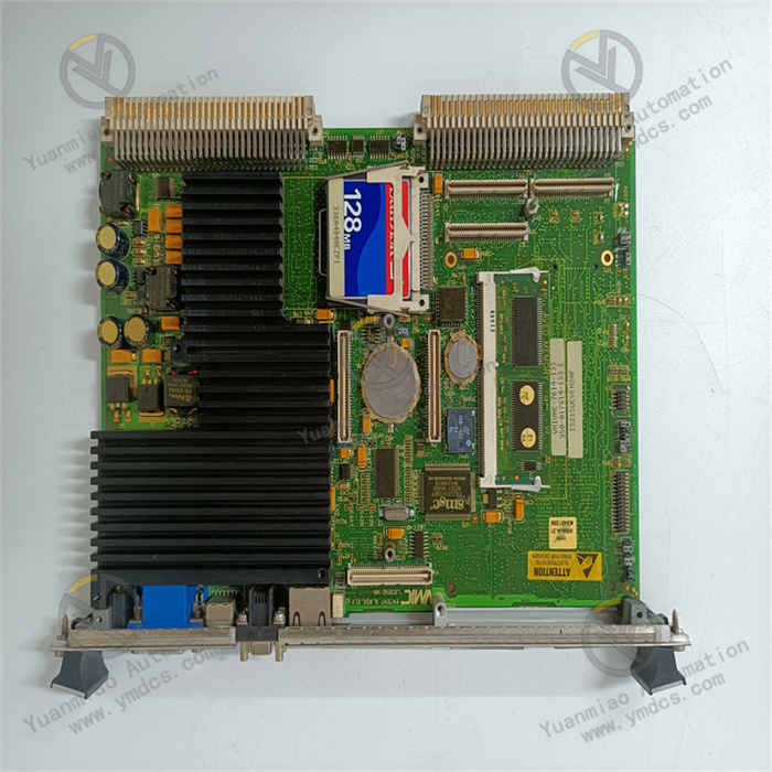
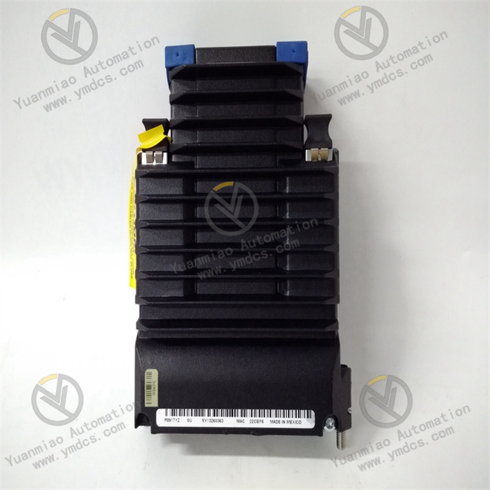
Foxboro FCP270 P0917YZ
The Foxboro FCP270 P0917YZ is a field control processor.
Hardware Configuration
- Memory: Equipped with 16MB SDRAM and 32MB flash memory, which can store control logic, historical data, configuration information, etc., providing necessary storage space for the processor's operation and data processing.
- Input Voltage: The redundant voltage is typically 24V DC. This redundant design improves power supply reliability, ensuring the system can still operate normally if one power supply fails.
- Dimensions and Weight: It measures 14.7 cm in length, 5.15 cm in width, and 11.4 cm in height, weighing 0.6 kg. Its compact size makes it easy to install in various industrial control equipment.
Performance Characteristics
- Strong Processing Capability: Adopts a high-performance processor that can quickly handle large amounts of data and complex control logic and algorithms, ensuring real-time and accurate control of various parameters in industrial production processes, such as temperature, pressure, flow, and liquid level.
- Rich Communication Interfaces: Features multiple communication interfaces, such as Ethernet, fiber optics, RS-232, and RS-485, facilitating communication with other control devices, sensors, actuators, and data acquisition systems to achieve automation and remote monitoring.
- High Reliability: Uses two control modules to provide patented fault-tolerant operation. If one module fails, the other can continue working, significantly improving system reliability. Meanwhile, it adopts a rugged die-cast aluminum housing, capable of operating in harsh G3-class environments, and has passed CE certification to ensure product quality and safety in harsh industrial environments.
Application Fields
- Chemical Industry: Used for reactor control, material transportation control, distillation column control, etc., in chemical production processes to achieve precise monitoring and optimization of chemical production and ensure product quality and production safety.
- Power Industry: Can be applied to generator set control in power plants, substation automation control, etc., to monitor and control various parameters in power production and transmission processes in real time, ensuring the stable operation of power systems.
- Water Treatment Industry: Used in sewage treatment plants, waterworks, and other facilities to control the operation of equipment such as pumps and valves, achieving precise control of parameters such as water quality, water level, and flow to ensure the efficient operation of water treatment processes.
- Oil and Gas Industry: Used to control and monitor various production equipment in oil extraction, refining, and natural gas transportation to achieve automation and optimization of production processes and improve production efficiency and safety.
The Foxboro FCP270 P0917YZ is an industrial controller commonly used in process automation systems. Below is a compilation of common faults, possible causes, and solutions for reference:
1. Power Supply Faults
Fault Symptoms
- No power indicator (LED) on the controller.
- Frequent system restarts or failure to start.
Possible Causes
- Abnormal external power supply: Unstable input voltage, loose or damaged power cables.
- Power module failure: Burned internal power module, aged capacitors, or damaged components.
- Motherboard short circuit: Component failures on the motherboard causing power overload.
Solutions
- Check external power supply:
- Measure the input voltage with a multimeter (typically DC 24V) to ensure it is within the rated range (±10% fluctuation).
- Replace the power cable or check the power outlet to ensure a secure connection.
- Replace the power module:
- Confirm whether the power module of the controller model is detachable (some models have integrated motherboards) and contact the manufacturer or professional personnel to replace the original power module.
- Troubleshoot motherboard short circuits:
- Disconnect all external modules (e.g., I/O cards) and test the power supply alone. If it recovers, the short circuit may be caused by external modules; if the fault persists, return the motherboard for repair.
2. Communication Faults
Fault Symptoms
- Failure to communicate with the host computer (e.g., DCS system, HMI).
- Abnormal flashing or Extinguished of communication indicator lights (e.g., Ethernet, serial port LED).
- Interrupted data transmission, packet loss, or high error rates.
Possible Causes
- Damaged communication interface: Physical damage to Ethernet or serial ports (e.g., bent or oxidized pins).
- Incorrect parameter configuration: IP address conflicts, mismatched baud rates/protocols, or incorrect communication protocol settings (e.g., Modbus, Profinet).
- Network equipment failure: Faulty switch ports, poor Ethernet cable connector contact, or excessive fiber link loss.
- Firmware version issues: Incompatibility between the controller firmware and communication protocol version.
Solutions
- Check physical connections:
- Replace network cables or fiber optic cables and use a cable tester to check line connectivity.
- Clean the interface pins to ensure no oxidation or foreign matter.
- Reconfigure parameters:
- Ensure the controller's IP address is in the same network segment as the host computer and conflict-free (can be assigned via DHCP or statically).
- Verify that serial port parameters (baud rate, data bits, stop bits, parity) match the device.
- Test network equipment:
- Directly connect the controller to a computer and use the ping command to test network connectivity (e.g., ping the controller's IP).
- Replace switch ports or test other network devices (e.g., routers).
- Upgrade firmware:
- Download the latest firmware from the Foxboro official website and upgrade it via specialized tools (e.g., Foxboro Control Studio) (operate with caution to avoid firmware corruption due to power outages).
3. I/O Module Faults
Fault Symptoms
- Abnormal input/output signals (e.g., analog data fluctuations, digital signal unresponsiveness).
- Abnormal indicator lights on I/O modules (e.g., channel fault lights).
- Overheating or unusual noise from the module.
Possible Causes
- Module hardware damage: Internal chip failures, loose terminal connections, or component aging.
- Signal interference: Parallel installation of high-voltage lines and signal lines causing electromagnetic interference (EMI).
- Wiring errors: Mismatched input/output types (e.g., AI/AO/DI/DO) or reverse polarity.
- Overload or short circuit: External equipment failures causing module channel overload (e.g., current exceeding the rated value).
Solutions
- Check wiring:
- Confirm correct wiring against the schematic, especially the positive/negative polarity of analog signals and shield grounding.
- Re-plug terminal connections to ensure good contact.
- Isolate interference sources:
- Lay signal cables separately from power cables and use shielded cables with reliable grounding.
- Install filters or surge protectors at signal input ends.
- Replace modules or channels:
- If a single channel fails, try switching to a backup channel and reconfiguring.
- If the entire module fails, power off and replace it with the same model, then redownload the configuration.
- Test external equipment:
- Use a multimeter to measure external signals (e.g., sensor outputs) to exclude on-site equipment failures.
4. System Program Faults (Logical Errors)
Fault Symptoms
- Abnormal control logic (e.g., valves not operating as expected, PID regulation failures).
- Program runtime interruptions with error codes (e.g., "program verification failed").
- Loss or failure to load configuration files.
Possible Causes
- Program errors: Syntax errors, infinite loops, or resource conflicts in user-written control logic.
- Corrupted configuration files: File loss or damage due to storage medium (e.g., CF card, SSD) failures.
- Insufficient memory: Program resource usage exceeding the controller's memory limits.
Solutions
- Check program logic:
- Use Foxboro programming software (e.g., I/A Series Engineering Workstation) to debug programs and identify syntax errors or logical flaws.
- Test the program in segments to locate abnormal modules or function blocks.
- Restore configuration files:
- Restore configuration files from backups (regular backups to external storage are recommended).
- If the storage medium is damaged, replace the CF card/SSD and redownload the program.
- Optimize program resources:
- Reduce redundant instructions, merge duplicate function blocks, and free up memory space.
- Ensure the controller's hardware configuration (e.g., memory, CPU performance) meets program requirements.
5. Overheating or Cooling Faults
Fault Symptoms
- Excessively high controller housing temperature.
- Unusual fan noise or fan stoppage.
- Automatic system restarts or shutdowns due to overheating.
Possible Causes
- Cooling fan failure: Dust-clogged fans, worn bearings, or power supply failures.
- Poor installation environment: Inadequate ventilation, excessively high cabinet temperatures (exceeding the rated operating temperature range, typically 0–60°C).
- Dusty heat sinks: Dust accumulation on internal heat sinks affecting heat dissipation efficiency.
Solutions
- Clean fans and heat sinks:
- Power off and use compressed air to blow out dust and debris from fans and heat sinks.
- Check fan rotation for smoothness; replace with new fans if stuck or making unusual noises.
- Improve the installation environment:
- Ensure good cabinet ventilation and install fans or air conditioners to control temperature.
- Avoid placing the controller near heat-generating equipment (e.g., inverters, high-power supplies).
- Check cooling design:
- Confirm correct controller installation (e.g., loose rail mounting affecting heat dissipation contact).