Description
GE DS200TCQAG1BHF-W01
I. Overview
The GE DS200TCQAG1BHF-W01 is a critical analog input/output board belonging to GE's classic MARK V series distributed control system (DCS). In the field of industrial automation, especially in scenarios with extremely high requirements for system reliability and signal processing accuracy, this board plays an indispensable role. Specifically designed for complex industrial environments, it enables seamless integration with various sensors, actuators, and supervisory control systems, undertaking the tasks of analog signal acquisition, processing, and output, providing solid support for the stable operation of the entire control system.
In terms of application scenarios, in the power industry, the DS200TCQAG1BHF-W01 can accurately collect analog signals such as temperature, pressure, and flow from large thermal power plants (for real-time monitoring and control of boiler, turbine, and other equipment operating parameters) and new energy power stations (for production process management of hydropower, wind power, etc.), and transmit processed signals to the control system to ensure efficient and stable operation of power generation equipment. In the petrochemical industry, from crude oil extraction and refining to the production of various chemical products, the entire process involves numerous complex physical and chemical reactions, requiring strict control of many process parameters. With its excellent performance, this board can accurately process relevant analog signals, helping petrochemical enterprises achieve safe production, improve production efficiency, and reduce energy consumption. In the metallurgical industry, such as in the processes of blast furnace ironmaking, converter steelmaking, and steel rolling in steel production, accurate monitoring and control of key parameters like temperature and pressure directly affect product quality. The DS200TCQAG1BHF-W01 provides strong support for optimized control of metallurgical production processes through its reliable signal processing capabilities. Additionally, it is widely used in cement plants, paper mills, marine power control systems, and other fields due to its superior performance.
II. Technical Parameters
1. Power Parameters
- Voltage: The operating voltage is +24VDC, with a certain voltage tolerance range, enabling adaptation to output fluctuations of most industrial power systems and providing reliable power support for stable device operation.
- Current: The power requirement is 500mA. The low current consumption helps reduce the overall system power consumption, in line with the industrial development trend of energy conservation and environmental protection.
2. Electrical Parameters
- Analog Input:
- Number of Channels: Equipped with 32 analog input channels, enabling simultaneous connection of multiple analog sensors to meet the needs of large-scale data acquisition.
- Input Range: The input signal range is -10V to +10V, capable of adapting to output signals from various types of analog sensors, greatly improving the device's versatility.
- Analog Output:
- Number of Channels: Featuring 16 analog output channels, providing analog control signals to actuators and other devices.
- Output Range: The output signal range is -10mA to +10mA, capable of providing precise analog drive signals that meet the working requirements of actuators.
- Accuracy: This board has high signal processing accuracy. Within the entire working range, the measurement accuracy can reach ±0.25%, enabling extremely accurate conversion of analog signals into digital signals for subsequent processing and output, providing a reliable data foundation for industrial applications with strict measurement accuracy requirements.
- Isolation Voltage: The isolation voltage between input and output, as well as between the device and external circuits, is as high as 2500Vrms, effectively achieving electrical isolation. This can largely prevent external interference signals from affecting the device's internal circuits while avoiding interference generated by the device itself from affecting other equipment, improving the device's anti-interference capability and operational stability in complex electromagnetic environments.
3. Communication Parameters
- Communication Interface: Equipped with a standard RS485 communication interface, which is widely used in industrial communication for its advantages of long transmission distance and strong anti-interference capability. Through the RS485 interface, the DS200TCQAG1BHF-W01 can conveniently and stably communicate data with other devices, achieving efficient data interaction whether connected to a host computer control system or forming an industrial automation network with other intelligent devices to ensure collaborative operation of the entire system. Additionally, this board supports the Modbus RTU communication protocol, further enhancing its compatibility and interoperability with different devices.
4. Other Parameters
- Operating Temperature Range: Capable of stable operation in the extreme temperature range of -40°C to +70°C, adapting to various harsh industrial environment temperature conditions. It can operate normally in industrial facilities in cold polar regions or factories in hot desert areas, ensuring continuous and stable system operation.
- Humidity Range: Can work reliably in an environment with a relative humidity of 5% to 95% (non-condensing), demonstrating good adaptability to humidity environments and reducing the risk of device failure due to humidity changes.
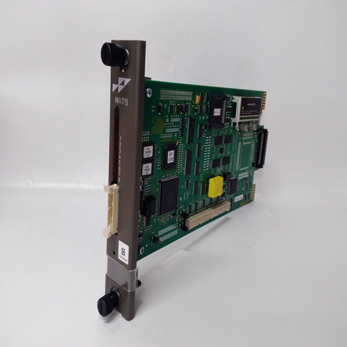
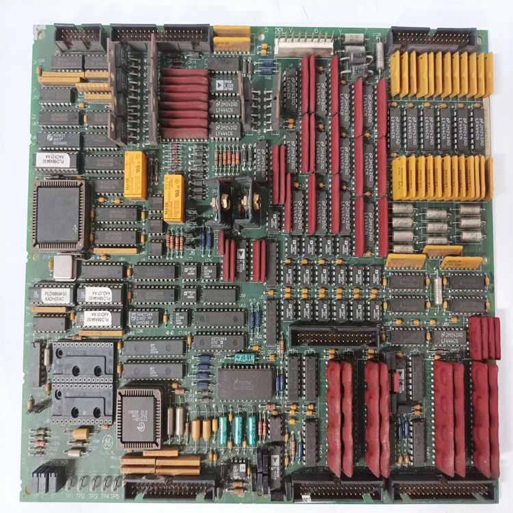
- Mechanical Structure: The board is designed with 6 mounting holes, facilitating secure installation in the driver's board cabinet using washers and screws. Its compact size offers obvious advantages in installation environments with limited space, such as industrial control cabinets, enabling flexible layout and installation to save valuable space. Meanwhile, the board is equipped with four 34-pin connectors, two 40-pin connectors, and six jumpers, enhancing the flexibility and configurability of its connection with external devices to facilitate user connection and setting according to actual needs. Additionally, the board is equipped with 6 LED indicators, which can intuitively display the device's working status, signal transmission conditions, etc., facilitating equipment monitoring and fault troubleshooting by operators.
III. Working Principle
1. Analog Signal Input Processing
When analog signals from various sensors (such as temperature sensors, pressure sensors, flow sensors, etc.) are connected to the analog input channels of the DS200TCQAG1BHF-W01, they first pass through the input buffer circuit. The role of this circuit is to initially isolate and buffer the input signals, preventing the input signals from adversely affecting subsequent processing circuits while improving the signal driving capability. The signals then enter the signal conditioning circuit, where they are amplified, filtered, and processed as needed. For example, if the input signal amplitude is small, it is amplified by an operational amplifier to reach a range that the A/D converter can effectively process; high-frequency noise mixed in the signal is filtered out by a low-pass filter to improve signal quality. The conditioned analog signals are then sent to the A/D converter, which converts the analog signals into digital signals for subsequent digital signal processing by the digital signal processor (DSP). The DSP calibrates, linearizes, and processes the converted digital signals to eliminate nonlinear errors and other measurement errors of the sensor, ultimately obtaining digital signal data that accurately reflects the measured physical quantity.
2. Digital Signal Processing and Communication
The digital signal processor analyzes and computes the processed digital signal data, generating corresponding control instruction data according to the system's pre-set control strategies and algorithms. These control instruction data are packaged and encoded according to the Modbus RTU communication protocol through the communication interface circuit, and then sent to the host computer control system or other devices requiring data reception through the RS485 communication interface. Meanwhile, the board can also receive instructions and parameter setting information from the host computer control system, and the digital signal processor adjusts the signal processing flow and control strategy based on the received information to achieve real-time and flexible control of the entire control system.
3. Analog Signal Output Processing
When the digital signal processor receives an instruction to output an analog control signal, it sends the corresponding digital control signal data to the D/A converter. The D/A converter converts the digital signal into an analog signal, which then passes through the output buffer circuit and signal conditioning circuit. The output buffer circuit is used to isolate the D/A converter from external loads, protecting the D/A converter from load changes; the signal conditioning circuit amplifies, filters, and processes the analog output signal to meet the input requirements of the actuator. For example, the signal amplitude is adjusted to the range where the actuator can work normally, and possible high-frequency interference signals are filtered out. Finally, the processed analog control signal is transmitted to actuators such as control valves and motor drivers through the analog output channel, thereby achieving precise control of industrial production processes.
4. Fault Detection and Diagnosis
The DS200TCQAG1BHF-W01 has a built-in perfect fault detection and diagnosis mechanism. During signal acquisition and processing, it real-time monitors parameters such as the amplitude and frequency of input signals. Once signal anomalies are found, such as signals exceeding the normal working range or signal loss, it immediately triggers a fault alarm. At the same time, the board self-checks its hardware circuits, including periodic functional detection of key components such as A/D converters, D/A converters, digital signal processors, and communication interface circuits. If a hardware component failure is detected, it is indicated by the LED indicators on the board, and the fault information is sent to the host computer control system through the communication interface, enabling operators to promptly troubleshoot and repair faults to ensure the reliability and stability of the entire control system.