Description
1. Overview
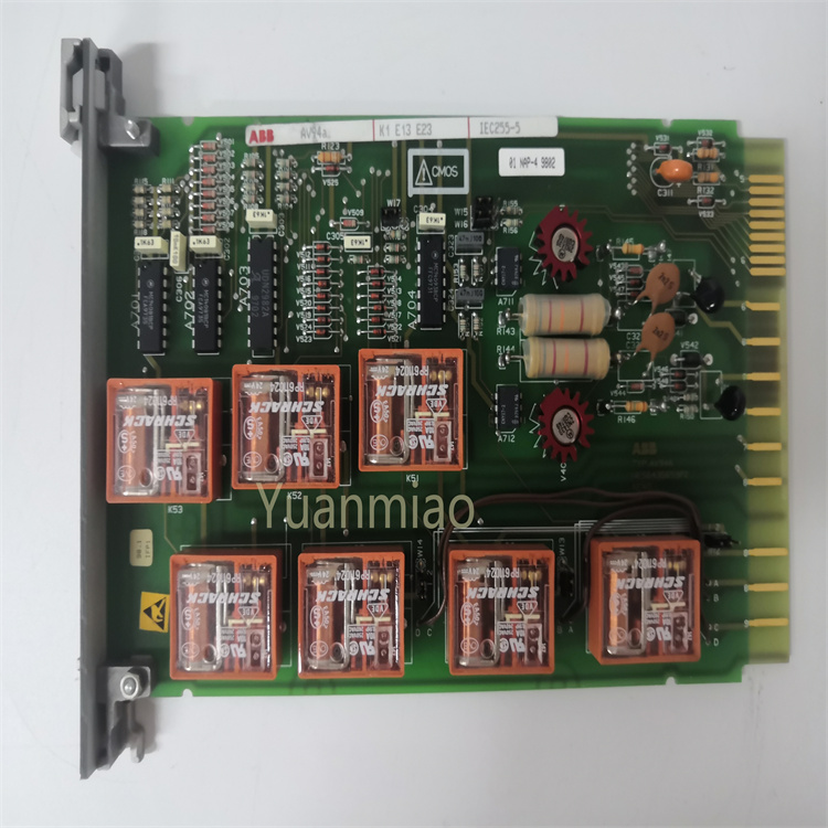
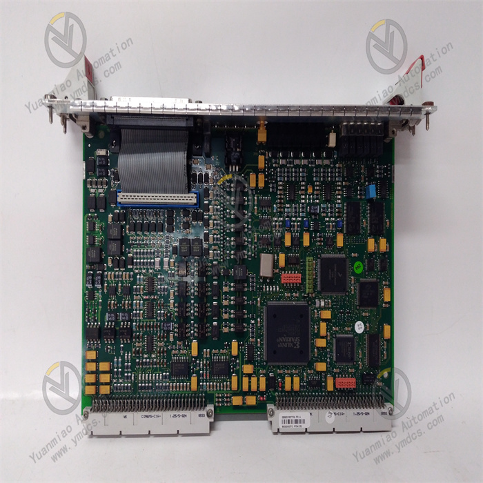
ABB PFSK141 (Part No. 3BSE006513R1) is a fiber‑optic communication board for excitation systems within the ABB Industrial IT series. Designed for the ABB UNITROL generator excitation control system, it acts as the core interface board for fiber‑optic signal transmission between the excitation regulator, power unit and system main controller. It is mainly used for isolated transmission of pulse signals, fiber‑optic data transceiving, loop status feedback and high‑speed system communication in excitation systems. It is widely deployed in ABB UNITROL 5000 and UNITROL 6000 excitation systems for thermal‑power, hydro‑power and gas‑turbine generator sets.
Adopting an all‑fiber‑optic isolated transmission architecture, the PFSK41 board eliminates signal anomalies caused by electrical interference, ground‑potential difference and loop crosstalk. It features high insulation, strong anti‑interference performance and high transmission real‑time performance. Integrated with signal decoding, photoelectric conversion, fault detection and status feedback functions, it realizes accurate isolated transmission of excitation trigger pulses and real‑time feedback of power‑bridge operating status, ensuring the regulation accuracy and operational stability of excitation systems. It is a key dedicated spare part for power‑plant excitation‑system maintenance, replacement of aged boards and system upgrade & retrofit.
2. Functions and Features
2.1 Core Functions
Isolated Fiber‑optic Transmission of Excitation Pulses: Performs photoelectric conversion and isolated transmission of thyristor trigger pulses issued by the excitation main controller. Low‑voltage control signals are transmitted losslessly to the excitation power rectifier unit via optical fiber, achieving complete electrical isolation between the control loop and high‑voltage power loop and preventing high‑voltage crosstalk from damaging main‑controller equipment.
Bidirectional High‑speed Data Communication: Supports bidirectional signal interaction for excitation systems. Forward direction transmits trigger pulses, regulation commands and control parameters; reverse direction collects power‑bridge operating status, thyristor conduction feedback and loop abnormal signals to form a data‑interaction link for closed‑loop excitation control.
Multi‑channel Fiber‑optic Signal Transceiving: Equipped with multiple independent fiber‑optic transceiving channels for signal transmission to multiple groups of excitation power rectifier bridges. It meets control requirements for multi‑bridge parallel excitation architectures of large‑scale units and fits excitation‑regulation scenarios for large‑capacity generator sets.
Real‑time Loop‑status Monitoring: Continuously monitors fiber‑optic link on‑off status, signal loss, pulse anomalies and channel faults. Fault information is uploaded to the excitation main controller in real time, providing accurate data support for fault alarms, logic interlocks and anomaly tracing.
Signal Shaping and Error‑correction Processing: Built‑in signal‑shaping, filtering and fault‑tolerant‑processing logic filters clutter signals induced by on‑site electromagnetic interference and corrects minor signal distortion during transmission to guarantee precise pulse timing and stable waveforms.
Hardware‑based Fault Self‑diagnosis: Automatically completes channel self‑test, photoelectric‑module inspection and link‑initialization verification upon power‑on. During operation, it continuously monitors board power supply, fiber‑optic channels and chip operating status to accurately identify channel failure, fiber breakage and module faults.
System Interlock‑protection Coordination: When severe faults such as fiber‑optic link interruption, pulse‑transmission failure and channel abnormality are detected, it cooperates with the main controller to trigger excitation block, alarm prompts and safety‑interlock logic, avoiding hazardous conditions including excitation runaway and false triggering of power bridges.
2.2 Product Characteristics
Complete Electrical Isolation for Superior Safety: Contact‑free fiber‑optic transmission fully isolates low‑voltage control loops from high‑voltage power loops. Risks of ground‑potential difference, high‑voltage crosstalk and electric leakage are eliminated, greatly raising the electrical‑safety level of the excitation system.
Excellent Anti‑interference Performance: Immune to on‑site high‑frequency harmonics, intense electromagnetic radiation, variable‑frequency interference and electrostatic induction. No signal jitter or pulse offset occurs, making it suitable for harsh high‑EMI conditions in power plants.
High Transmission Real‑time Performance and Precise Timing: High‑speed photoelectric conversion delivers extremely low pulse‑transmission latency and good timing consistency. It ensures accurate triggering of excitation thyristors and secures linearity and stability of excitation regulation.
High Integration and Outstanding Stability: A single board integrates photoelectric conversion, signal processing, fault diagnosis and status‑feedback functions. Built with industrial‑grade components, it supports 7×24‑hour continuous long‑term operation without operational drift or parameter offset.
Full Native Compatibility with Original Systems: Natively compatible with the full range of ABB UNITROL 5000 and UNITROL 6000 excitation‑control systems. Communication protocols, signal logic and channel definitions are fully matched. No program modification is required after replacement for direct commissioning.
Convenient Operation‑Maintenance and High Fault Tolerance: On‑board status LEDs intuitively indicate channel operation, faults and link status for fast fault localization. Replacement is allowed during shutdown maintenance. Failure of one single channel will not impair operation of other channels, granting strong system fault‑tolerance capability.
3. Specifications
| Item | Specifications |
|---|---|
| Model | PFSK141 |
| Part Number | 3BSE006513R1 |
| Device Type | Fiber‑optic Communication Interface Board for Excitation System |
| Brand & Manufacturer | ABB |
| Applicable System | ABB UNITROL 5000 / UNITROL 6000 Excitation Control System |
| Transmission Medium | Industrial Multi‑mode Optical Fiber |
| Core Functions | Photoelectric isolated transmission of excitation trigger pulses, channel status feedback, fault self‑diagnosis |
| Insulation Characteristics | Complete electrical isolation between low‑voltage and high‑voltage circuits, high dielectric withstand capability |
| Power Supply | Standard system low‑voltage DC power supply |
| Operating Temperature | 0 ℃ ~ +60 ℃ (rated industrial condition) |
| Storage Temperature | ‑40 ℃ ~ +85 ℃ |
| Ambient Humidity | 5%‑95%RH, non‑condensing |
| Mounting Method | Standard slot‑mounting in excitation cabinet |
| Operating Features | 7×24‑hour continuous operation, real‑time fault monitoring, signal fault‑tolerant processing |
4. Operating Principle
The ABB PFSK141 3BSE006513R1 board operates on a photoelectric‑isolated bidirectional‑transmission mechanism and serves as the signal‑isolation hub between the control layer and power layer of the excitation system. Upon power‑on, it automatically completes hardware self‑test, photoelectric‑module initialization, channel calibration and link detection. After confirming normal operation of all fiber‑optic channels and signal‑processing circuits, it enters standby‑running status.
During normal system operation, thyristor trigger pulses and regulation control signals issued by the excitation main controller are sent to the PFSK41 board as electrical signals. The photoelectric‑conversion modules convert electrical signals into optical signals, which are transmitted via fiber‑optic links to the excitation power rectifier unit to drive sequential thyristor conduction, realizing precise closed‑loop regulation of generator excitation current and voltage. Fiber‑optic transmission physically separates the control side from the high‑voltage power side and prevents main‑controller damage caused by high‑voltage reverse breakdown and loop interference.
Meanwhile, power‑unit operating status, thyristor conduction feedback and loop‑fault signals are sent back to this board through reverse fiber‑optic channels. After signal decoding, shaping and verification, data are uploaded to the excitation main controller for real‑time power‑loop status monitoring. The board continuously monitors fiber‑optic link connectivity, signal strength, pulse timing and channel status. Once fiber breakage, signal loss, pulse abnormality or channel fault is detected, fault status is latched, alarm information is uploaded, and excitation‑protection logic is triggered in coordination with the main controller to avoid excitation runaway and unit anomalies.
Embedded signal‑fault‑tolerance and shaping algorithms automatically filter clutter signals generated by on‑site electromagnetic interference and correct minor signal distortion. Stable pulse timing and accurate transmission are maintained, ensuring excitation‑system regulation stability under variable‑load, grid‑connection and steady‑state operating conditions.
5. Application Scenarios
Support for Excitation Systems of Large‑scale Generator Sets: Widely used in ABB UNITROL 5000 / 6000 excitation systems for thermal‑power, hydro‑power and gas‑turbine units. It undertakes core tasks of isolated excitation‑pulse transmission and power‑unit status monitoring to guarantee stable excitation regulation and reliable grid‑connected operation of generating units.
High‑low‑voltage Electrical‑isolation Protection: Meets isolation requirements between high‑voltage power loops and low‑voltage control loops in excitation systems. Complete electrical isolation is realized via fiber‑optic transmission to prevent board burnout and system faults induced by high‑voltage crosstalk and ground‑potential difference.
Maintenance‑oriented Replacement for Legacy Excitation Systems: Used for replacement of faulty and aged PFSK41 boards in legacy ABB excitation systems to resolve signal‑transmission anomalies, channel failure and frequent alarms. Equipment service can be quickly restored without modifying system wiring or programs.
Excitation Control under High‑interference Conditions: Adapts to heavy‑EMI power‑plant environments with dense frequency converters, high‑voltage equipment and high‑power motors. Fiber‑optic interference‑free transmission eliminates signal jitter, pulse offset and excitation‑regulation drift.
Multi‑bridge Parallel Excitation Architectures: Suits large‑capacity excitation systems with parallel rectifier bridges. Trigger pulses are synchronously transmitted through multiple fiber‑optic channels to ensure synchronized thyristor conduction, balanced voltage and balanced current across bridges, improving stability of high‑power‑unit excitation systems.
6. Troubleshooting
6.1 Abnormal excitation pulses and fluctuating unit excitation regulation
Root Causes: Fiber‑optic‑channel signal attenuation, bent or damaged optical fiber, aging photoelectric‑conversion modules, faulty signal‑shaping circuits, channel‑timing offset.
Solutions: Inspect fiber‑optic cables; replace aged, bent or contaminated optical fibers and clean fiber‑optic connectors. Test signal‑transmission status of each channel and calibrate pulse timing. Inspect board signal‑processing circuits and remove dust and oxidation layers. If faults persist after field rectification, hardware aging of the board is confirmed and PFSK41 shall be replaced.
6.2 System reports fiber‑optic‑link fault and channel‑disconnection alarms
Root Causes: Loose fiber‑optic connectors, broken optical fiber, failed photoelectric transceivers, damaged on‑board channel circuits, unstable power supply.
Solutions: Power off and check fiber‑optic connector insertion status; re‑seat, fasten and clean connector end faces. Test continuity of each fiber‑optic path and replace faulty fiber‑optic links. Verify board input power supply and eliminate voltage‑fluctuation risks. Replace the spare board if channel faults are still reported with intact links, indicating damaged on‑board channels.
6.3 Abnormal power‑bridge status feedback and signal loss
Root Causes: Faulty reverse feedback channels, defective signal‑decoding circuits, excessive fiber‑optic signal attenuation, abnormal feedback signals from power units.
Solutions: Verify normal operation of power‑unit feedback loops. Test transmission quality of reverse fiber‑optic channels, optimize fiber routing and reduce signal attenuation. Validate on‑board signal‑decoding and shaping functions. Replace the board if external loops are normal yet signal‑processing‑unit failure is confirmed.
6.4 Power‑on self‑test failure and board initialization failure
Root Causes: Abnormal board power supply, defective core chips, total failure of photoelectric modules, abnormal board firmware.
Solutions: Measure board input supply voltage and eliminate power loss, under‑voltage and voltage‑fluctuation issues. Re‑insert the board and clean oxidation contaminants on slots and gold fingers. Reboot the system for re‑initialization. Directly install a brand‑new PFSK41 board if self‑test still fails with proper power supply and contact.
6.5 Frequent false alarms and signal disorder under high‑interference conditions
Root Causes: Fiber‑optic routing runs close to high‑interference equipment, degraded board anti‑interference performance, external clutter interfering with signal decoding.
Solutions: Optimize fiber‑optic routing paths and keep cables away from high‑voltage, variable‑frequency and high‑power interference sources. Rearrange cabinet wiring to reduce electromagnetic coupling interference. Verify on‑board signal‑fault‑tolerance functions. Replace the board if faults persist after environmental rectification, indicating degraded board performance.