Description
1. Overview
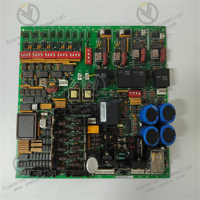
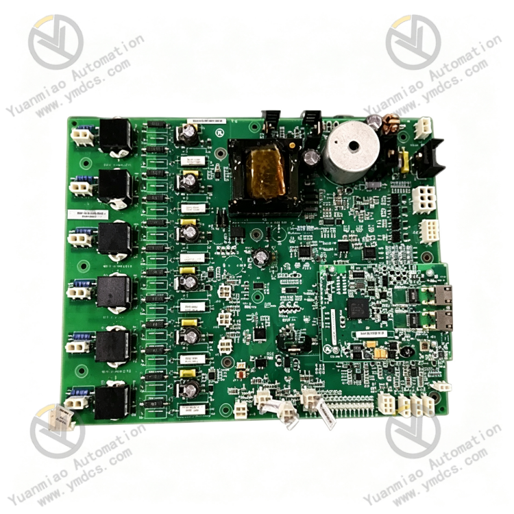
The IS200EBRGH1A is an Exciter Bridge Interface Board designed by General Electric (GE) for the EX2100e excitation control system and Speedtronic Mark VIe turbine control system. As a core control PCB for generator excitation systems in power plants, it is widely deployed in thermal power plants, gas turbines and combined‑cycle power plants for generator excitation regulation, rectifier bridge drive, temperature monitoring and fault interlock protection.
Serving as a dedicated signal‑interaction hub between the excitation main controller and the power rectifier bridge, this board performs key functions including excitation pulse drive, power‑loop status acquisition, cooling‑fan speed regulation, multi‑point temperature monitoring and safety fault interlock. It integrates high‑voltage pulse amplification, hardware self‑diagnosis, on‑board data storage and redundant data synchronization. It is adapted to harsh plant conditions featuring high temperature, vibration and strong electromagnetic interference. With merits of stable operation, low long‑term drift, hot‑swap support and bumpless redundant switching, it is a critical spare part for routine excitation‑system maintenance, legacy board replacement and excitation‑loop upgrading.
2. Functions and Features
2.1 Core Functions
Excitation‑bridge Pulse Drive and Signal Amplification: Built‑in high‑voltage pulse‑amplifying circuits convert low‑level control signals from the main controller into high‑voltage drive pulses to precisely trigger the excitation power rectifier bridge. Millisecond‑level fast response ensures reliable performance during excitation system startup/shutdown, load ramping and steady‑state regulation.
Real‑time Full‑condition Status Monitoring: Continuously collects excitation‑bridge conduction status, loop current, operating voltage and power‑unit operating conditions, and uploads data to the EX2100e main controller to realize closed‑loop precise excitation regulation and capture abnormal condition fluctuations in a timely manner.
Multi‑channel RTD Temperature Acquisition and Over‑temperature Protection: Equipped with 4 independent RTD channels supporting single‑mode / dual‑mode RTD acquisition. It monitors temperatures of excitation power modules, rectifier bridges and cabinet internals. Alarms and protection logic will be triggered once thresholds are exceeded to prevent thermal burnout of power devices.
PWM Intelligent Cooling Speed Control: Dynamically adjusts cooling‑fan speed via pulse‑width‑modulation signals. Cooling capacity is automatically matched according to unit load and component temperature to maintain constant‑temperature operation and avoid insufficient cooling at low temperature or excessive loss at high temperature.
Multi‑channel Fault Interlock Protection: Provides 2 dedicated fault‑input channels for real‑time detection of excitation‑loop faults such as short‑circuit, overload, component failure and cooling anomaly. Safety unit‑trip interlock will be activated immediately upon abnormality to prevent major accidents caused by operation under faulty conditions.
Board Identification and Firmware Storage: On‑board dedicated memory stores board model, serial number and hardware‑version information. Automatic system identification matches firmware and configuration parameters at power‑on, effectively avoiding board mismatch, parameter incompatibility and protocol‑mismatch issues.
Comprehensive Hardware Self‑diagnosis: Automatic hardware initialization and self‑test at power‑on. During operation, it continuously monitors board power supply, bus communication, channel status, output loops and thermal conditions. Fault points are accurately located and fault codes are uploaded to reduce on‑site troubleshooting workload.
TMR Seamless Redundant Switching: Natively supports Triple‑Modular‑Redundancy architecture. Multiple boards synchronize and cross‑check data in real time. Millisecond‑level bumpless switch‑over occurs upon single‑board failure without excitation interruption or unit trip, meeting zero‑downtime requirements for power‑plant operation.
2.2 Product Characteristics
High Integration and Compact Layout: A single board integrates pulse drive, temperature acquisition, fault monitoring, fan speed control and board identification. No extra expansion modules are required. It simplifies excitation‑system hardware architecture and field wiring and reduces potential fault points.
Fast Response and High Regulation Accuracy: Millisecond‑level signal conversion and pulse output. Excellent linearity with negligible lag and drift, fully satisfying control demands for unit grid‑connection, load variation and steady‑state operation.
Industrial‑grade High Anti‑interference Performance: Optimized circuit design for harsh plant environments with heavy EMI, high‑frequency harmonics, mechanical shock and temperature cycling. It effectively suppresses field noise and prevents signal jitter, accidental pulse triggering and logic disorder.
High‑reliability Redundant Operation: TMR fault‑tolerant operation ensures that single‑channel or single‑board faults do not impair overall system output, greatly improving excitation‑system stability and unit safety level.
Hot‑swappable for Maintenance: Standard slot‑mount form factor compatible with EX2100e racks. Easy assembly and disassembly allows faulty‑board replacement while the unit remains online to guarantee production continuity.
Full Native System Compatibility: Purpose‑built for GE EX2100e excitation systems and Speedtronic Mark VIe turbine control systems. Bus protocols, redundancy mechanisms and configuration logic are fully matched for plug‑and‑play replacement without extensive program or parameter modification.
3. Specifications
| Item | Specifications |
|---|---|
| Model | IS200EBRGH1A |
| Device Type | Exciter Bridge Interface Board |
| Applicable Systems | GE EX2100e Excitation Control System, Speedtronic Mark VIe Turbine Control System |
| Supported Architecture | TMR Triple‑Modular Redundancy Fault‑tolerant Architecture |
| Power Supply | 125 VDC System‑specific Power Supply |
| Nominal Frequency | 50 Hz / 60 Hz Dual‑frequency Compatibility |
| Temperature Channels | 4‑channel RTD acquisition, supports single‑mode / dual‑mode measurement |
| Fault Detection Channels | 2 dedicated fault‑input channels with safety‑trip interlock support |
| Main Output Functions | High‑voltage Pulse Drive, PWM Cooling‑fan Speed Control |
| On‑board Storage | Permanent storage of board model, serial number and firmware version |
| Status Indicators | Gate supply, trigger status, alarm, bridge temperature, current status |
| Operating Temperature | 0 ℃ ~ +40 ℃ (rated operating condition) |
| Storage Temperature | ‑40 ℃ ~ +85 ℃ |
| Mounting | Standard rack slot‑mount installation |
4. Operating Principle
The IS200EBRGH1A Exciter Bridge Interface Board adopts a closed‑loop workflow: Command Reception — Pulse Amplification & Drive — Status Acquisition & Monitoring — Intelligent Thermal Control — Fault Protection & Interlock. At power‑on, the board completes hardware self‑test, firmware identification, bus‑protocol matching and system timing synchronization. After loading excitation‑regulation parameters, protection thresholds and PWM control logic from the main controller, it enters normal operation.
During runtime, the board receives excitation commands from the EX2100e controller. Internal high‑voltage pulse‑amplifying circuits convert low‑level control signals into high‑voltage drive pulses to control turn‑on / turn‑off of the excitation rectifier bridge, realizing closed‑loop dynamic regulation of generator excitation current and voltage and keeping excitation parameters stable during grid‑connection, load ramping and steady‑state operation.
Meanwhile, four RTD channels continuously sample temperatures of excitation power modules, rectifier bridges and cabinet internals. Combined with PWM speed‑regulation logic, cooling‑fan speed is adjusted dynamically according to unit load and temperature to maintain constant‑temperature equipment operation. Two fault‑detection channels continuously scan the excitation loop for hazards including short‑circuit, overload, component failure and cooling loss.
On‑board memory performs board identification and firmware matching to ensure stable bus communication and correct parameter adaptation. Once over‑temperature, loop fault, communication failure or pulse‑output loss is detected, fault status is latched, fault codes are uploaded and safety‑trip interlock is activated to avoid power‑device burnout and unit trip. Under TMR configuration, multiple boards acquire data synchronously and cross‑validate each other. Bumpless automatic switch‑over takes place upon single‑board failure to guarantee uninterrupted excitation output.
5. Application Scenarios
Excitation Systems for Large Thermal Power Units: Deployed in 300 MW, 600 MW, 1000 MW and other major thermal‑power units equipped with EX2100e excitation systems. It undertakes excitation‑bridge drive, thermal protection, fault interlock and cooling control to ensure stable grid‑connected continuous operation.
Gas‑turbine and Combined‑cycle Unit Control: Compatible with Mark VIe control systems for gas‑turbine and combined‑cycle power plants. It implements precise excitation regulation and condition monitoring to meet high‑accuracy requirements under frequent start‑stop and fast‑load‑change conditions.
Redundant Fault‑tolerant Control for Power‑plant Excitation Systems: Applied in TMR‑based excitation architectures for critical units. Redundant switch‑over, self‑diagnosis and multi‑level protection prevent unplanned outages induced by excitation anomalies and improve unit reliability.
Retrofit of Legacy Excitation Systems: Replaces aged or defective boards of the same model to resolve issues such as excitation drift, temperature‑measurement failure and spurious interlock actuation. System architecture and wiring remain unchanged for fast hardware upgrade and improved overall system stability.
Thermal‑protection for Excitation Power Units: Satisfies high‑precision thermal‑management requirements for high‑power excitation rectifier bridges and power modules. Real‑time temperature monitoring, intelligent cooling adjustment and over‑temperature protection slow component aging and extend service life of excitation equipment.
6. Troubleshooting
6.1 Severe excitation‑parameter fluctuation and unstable regulation
Root Causes: Drift of board pulse‑output circuit, abnormal PWM parameters, poor terminal contact, severe on‑site electromagnetic interference, faulty temperature acquisition leading to incorrect cooling control.
Solutions: Inspect board slots and terminals; tighten loose connections and remove oxidation and dust. Optimize shielding and grounding and keep equipment away from high‑voltage variable‑frequency interference sources. Recalibrate excitation pulse‑output parameters and regulation thresholds. Verify integrity of RTD loops. If symptoms persist after field remediation, hardware aging is confirmed; replace the IS200EBRGH1A board.
6.2 Board not recognized by system, communication loss
Root Causes: Faulty on‑board memory chip, firmware‑version mismatch, oxidized backplane gold‑finger contact, 125 VDC supply fluctuation, bus‑link anomaly.
Solutions: Power off, extract the board, clean gold‑fingers and rack slots of contaminants and oxidation, then re‑seat firmly. Verify stability of the 125 VDC power supply and eliminate power‑loss or voltage‑variation risks. Re‑flash compatible original firmware and synchronize system configuration parameters. Replace the board if communication cannot be restored despite normal hardware and power supply.
6.3 Recurring over‑temperature and thermal alarms
Root Causes: Damaged RTD channels, degraded temperature sensors, loose/shorted sensor wiring, failed PWM fan output, blocked cabinet air duct, drift of on‑board temperature‑measurement circuitry.
Solutions: Test continuity of RTD sensors and loops channel‑by‑channel and replace defective sensors. Verify PWM fan‑output performance and troubleshoot fan‑control loops. Clean accumulated dust in cabinet air ducts and improve ventilation. Calibrate temperature‑channel accuracy. Replace the spare board if alarms persist despite normal field wiring.
6.4 Spurious fault interlock and unplanned unit trip
Root Causes: Drift of fault‑detection channels, spurious fault signals induced by field interference, corrupted board logic circuits, improperly set protection thresholds.
Solutions: Review and optimize fault‑interlock threshold parameters. Remediate shielding and grounding to eliminate EMI‑caused false signals. Reboot the system to solidify operating logic. Replace the IS200EBRGH1A board if spurious triggering continues after external interference is removed.
6.5 Redundant switch‑over failure and brief excitation dropout
Root Causes: Inconsistent firmware versions between primary and standby boards, mismatched redundancy‑configuration parameters, poor backplane synchronization‑link contact, degraded redundant circuitry on the board.
Solutions: Unify firmware versions and redundancy‑configuration parameters for primary and standby boards and re‑establish synchronization pairing. Clean backplane contact points for both boards and repair synchronization‑link faults. Perform simulated fault‑switch‑over tests. Replace the faulty board if switch‑over still fails with correct parameters and healthy links.
6.6 Abnormal fan speed control and loss of constant‑temperature regulation
Root Causes: Damaged PWM output circuit, incorrect speed‑control configuration, fan‑loop failure, drift of on‑board thermal‑control logic.
Solutions: Check and correct PWM speed‑control configuration parameters. Inspect fan power and control loops and eliminate external equipment faults. Calibrate on‑board thermal‑control output logic. Replace the board if speed‑control remains abnormal with intact external loops.