Description
1. Overview
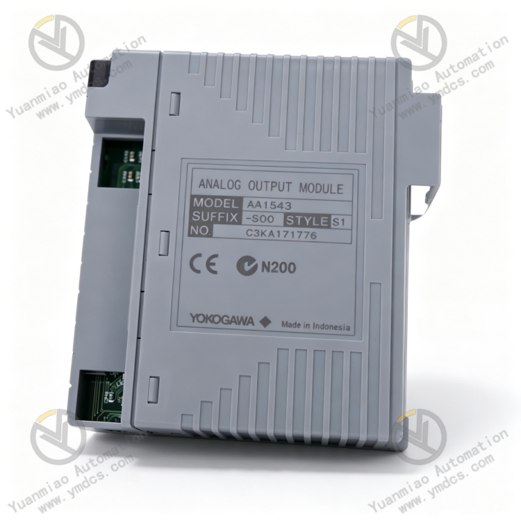
The Yokogawa AAI543‑S00 is a 16‑channel Isolated Analog Output (AO) Module, developed by Yokogawa Electric for the CENTUM VP / CS3000 distributed control system. As a high‑end core output hardware within the FIO series, it is widely deployed in high‑precision automatic‑control scenarios for continuous‑process industries including petrochemical, chemical, power, thermal‑power and metallurgy. This is the standard non‑HART version, featuring high channel density, high‑precision output, full electrical isolation and excellent system compatibility. It serves as the core hardware unit for closed‑loop regulation of field analog devices such as control valves, variable‑frequency drives and electric actuators.
The AAI543‑S00 is equipped with 16 independently electrically‑isolated output channels for high‑precision 4‑20 mA signal generation. Compared with conventional 8‑channel modules, it greatly improves cabinet space utilization. Adopting a high‑precision DAC conversion architecture, it delivers a fast 10 ms data update cycle, ultra‑low temperature drift and excellent linear output performance. It supports system redundant configuration and online hot‑swap maintenance. Certified for 1500 VAC electrical isolation, the module offers strong anti‑interference capability for harsh field conditions with heavy electromagnetic disturbance, temperature‑humidity fluctuations and long‑term continuous operation. It is a primary component for DCS system expansion, spare‑part replacement and legacy‑system upgrade projects for Yokogawa DCS installations.
2. Functions and Features
2.1 Core Functions
16‑channel high‑precision isolated analog output: 16 independent 4‑20 mA DC analog output channels with full galvanic isolation per channel. Faults, short‑circuits or load anomalies on one channel will not affect other channels, eliminating multi‑loop cascading failures and ensuring stable process control.
High‑speed real‑time closed‑loop regulation: 10 ms ultra‑fast data update cycle for rapid response to regulatory commands from the DCS controller. It dynamically adapts to changing process loads and supports fine tuning, steady‑state constant control and variable‑load regulation for flow, pressure, temperature, liquid‑level and other process parameters.
Accurate signal conversion and linear output: Equipped with industrial‑grade high‑precision DAC chips for outstanding full‑scale accuracy, minimal temperature‑drift error and superior linearity under all operating conditions. Free of output offset and step‑jitter artifacts, it meets demanding high‑precision requirements for fine chemical and precision temperature‑control applications.
Comprehensive hardware self‑diagnosis and alarm: Automatic power‑on initialization self‑test plus continuous runtime monitoring of channel open‑circuit, short‑circuit, overload, backplane bus communication faults, hardware malfunctions and power‑supply anomalies. Fault channels are precisely located with fault codes uploaded to facilitate fast maintenance troubleshooting.
Seamless redundant‑system support: Natively supports Yokogawa DCS redundant architecture with standard switch‑over logic. Dual redundant modules operate synchronously and perform bumpless automatic switch‑over upon failure without process disturbance or parameter jump, ensuring non‑stop production for critical units.
Fail‑safe hold mechanism: Locks current output values upon sudden communication loss, system disconnection or module abnormality. This prevents large‑stroke actuator movement and abrupt process parameter changes, avoiding production upsets and equipment safety incidents.
Standardized bus data exchange: Interfaces with Yokogawa proprietary high‑speed FIO backplane bus. It bi‑directionally transmits output status, channel conditions and fault information while receiving configuration parameters and control commands from the controller, enabling closed‑loop high‑precision regulation and remote maintenance management.
2.2 Product Characteristics
High channel density for cabinet space saving: 16 isolated outputs per module doubles channel count and reduces the quantity of installed modules and wiring complexity, conserving cabinet mounting space for high‑density automation‑system layouts.
Industrial‑grade high precision with low drift: Full‑scale output error ≤ ±48 μA; temperature drift ±16 μA/10 °C. Parameters remain stable across wide temperature ranges; output stays consistent during long‑term continuous operation with infrequent calibration requirements.
High‑withstand‑voltage galvanic‑isolation protection: 1500 V AC (1‑minute) isolation rating between output circuits and the system backplane. Effectively blocks field high‑voltage cross‑coupling, signal noise and loop interference to prevent signal distortion, module breakdown and cross‑talk across system loops.
Wide load compatibility: Accepts load resistance from 0 Ω to 750 Ω. Fully compatible with standard industrial control valves, variable‑frequency drives, valve positioners and electric actuators, covering most industrial analog control loops.
Non‑stop hot‑swap maintenance: Supports online hot‑swap replacement without system shutdown or process bypass operation. Module maintenance can be performed while the plant runs at full load, greatly shortening equipment downtime.
Full native OEM‑system compatibility: Natively compatible with the complete CENTUM VP / CS3000 DCS product line. Backplane bus, configuration logic and redundancy protocols are fully compliant. Replacement requires no parameter modification, reprogramming or wiring changes for plug‑and‑play operation.
3. Specifications
| Item | Specifications |
|---|---|
| Model | AAI543‑S00 |
| Device Type | 16‑Channel Isolated Analog Output Module (Standard AO) |
| Applicable System | Yokogawa CENTUM VP / CS3000 DCS |
| Channel Count | 16 channels, fully galvanically isolated per channel |
| Output Signal | Standard 4‑20 mA DC analog current signal |
| Output Accuracy | ±48 μA (0.3 % of full scale) |
| Temperature Drift | ±16 μA/10 °C, high stability over wide temperature range |
| Data Update Cycle | 10 ms high‑speed dynamic refresh |
| Permissible Load Resistance | 0 Ω ~ 750 Ω |
| Galvanic Isolation | 1500 V AC (1 min) between output side and system side |
| Communication | Standard version, no HART protocol |
| Redundancy | Supports system redundant configuration, standard switch‑over response |
| Power Consumption | 24 VDC supply, operating current approx. 680 mA |
| Operating Temperature | ‑20 °C ~ +70 °C (industrial wide‑range condition) |
| Storage Temperature | ‑40 °C ~ +85 °C |
| Ambient Humidity | 5 % ~ 95 % RH, non‑condensing |
| Ingress Protection | IP20 (for cabinet‑internal installation) |
| Mounting | Slot‑type stacking on standard FIO rack |
| Module Weight | Approx. 1.1 kg |
4. Operating Principle
The Yokogawa AAI543‑S00 analog output module implements a closed‑loop workflow: Bus Command Reception → Digital Signal Parsing → High‑precision DAC Conversion → Isolated Signal Output → Continuous Self‑diagnosis & Hold. Upon power‑on, the module completes hardware self‑test, channel initialization, bus protocol matching and system timing synchronization. After loading controller‑configured parameters including range, output limits and fail‑safe mode, it enters normal high‑precision output regulation mode.
Based on field process feedback, the DCS controller calculates digital control commands and transmits them to the module via the FIO backplane bus at a 10 ms cycle. The module processing unit decodes commands precisely. Sixteen independent high‑precision DAC circuits convert digital values linearly into 4‑20 mA analog current signals, which pass through galvanic‑isolation circuits to field control valves, variable‑frequency drives and actuators for accurate process adjustment and steady‑state control. Each channel operates with galvanic separation; load fluctuations or signal interference on one channel do not degrade output accuracy of other channels, ensuring stable multi‑loop simultaneous control.
During runtime, the module continuously monitors channel load conditions, output current, bus communication and hardware status. When channel short‑circuit, open‑circuit, overload or communication interruption is detected, self‑diagnosis protection activates: output values are latched and fault‑alarm codes are uploaded to prevent process upset. Under redundant configuration, dual modules perform real‑time data comparison and standby synchronization. Upon failure, bumpless automatic switch‑over takes over control without disturbance. After fault clearance and reset, the module resumes normal high‑precision output to maintain safe, stable and accurate automatic‑control‑system operation.
5. Application Scenarios
Petrochemical & chemical continuous‑process plants: Deployed in DCS systems for refining, coal‑chemical and fine‑chemical facilities. 16 channels centrally manage temperature, pressure, flow and liquid‑level control loops for reactors, distillation columns and heat‑exchange units to realize high‑precision coordinated multi‑loop control for stable continuous chemical production.
Thermal‑power & co‑generation automatic‑control systems: Applied to auxiliary control loops for boilers, steam turbines, desulfurization and denitrification in thermal‑power plants. Centrally governs feed‑water valves, air‑supply valves, induced‑draft valves and variable‑frequency equipment to stabilize unit load and operating parameters for long‑term full‑load power‑plant operation.
Metallurgy & building‑materials industrial automation: Used in automatic‑control systems for steel‑making, cement and kiln production lines. High‑density channels satisfy multi‑point actuator regulation requirements while resisting heavy vibration and electromagnetic interference for reliable production‑line performance.
DCS system expansion and intensive retrofit: Leverages 16‑channel high‑density design to replace legacy 8‑channel modules, reducing hardware count and wiring costs. Suitable for legacy‑system intensive upgrades and new control‑loop expansion projects.
Critical redundant industrial automatic‑control systems: Deployed on process‑critical non‑stop production units. Redundancy switch‑over and fail‑safe hold functions mitigate production outages caused by module faults and improve system fault‑tolerance and reliability.
6. Troubleshooting & Corrective Actions
6.1 Inaccurate channel output, process fluctuation, poor regulation linearity
Root Causes: DAC conversion accuracy drift, accumulated temperature‑drift over long runtime, mismatched field load resistance, signal‑loop interference, poor terminal‑block contact.
Corrective Actions: Compare configured set‑point against actual field feedback; perform accuracy calibration for deviant channels. Measure field load resistance to confirm it falls within 0‑750 Ω. Tighten terminals, optimize shielding & earthing and route cables away from variable‑frequency and high‑voltage noise sources. If inaccuracy persists after field‑loop rectification, hardware aging is indicated; replace AAI543‑S00 module.
6.2 Single‑channel / multi‑channel no output, actuator fails to respond
Root Causes: Channel not enabled in configuration, incorrect range parameters, damaged channel output circuitry, field‑loop open‑circuit / short‑circuit, oxidized or loose terminals.
Corrective Actions: Verify DCS configuration for channel enable status, range and direct/reverse‑action settings; correct invalid parameters. Power off and inspect terminals; remove oxidation, retighten connections and check for field‑loop breakage or equipment failure. If configuration and field wiring are intact yet output remains absent, channel hardware damage is confirmed; replace spare module.
6.3 Module communication fault, system cannot recognize module, no status upload
Root Causes: Poor contact of FIO backplane gold‑fingers, abnormal module power supply, bus‑link failure, corrupted firmware, defective communication unit.
Corrective Actions: Power off, extract module, clean gold‑fingers and rack‑slot contaminants, re‑seat firmly. Measure 24 VDC supply voltage and operating current to rule out power loss or voltage fluctuation. Restart DCS bus service and refresh module firmware and configuration. If hardware links remain intact with no communication recovery, replace module directly.
6.4 Frequent module alarms, random errors, unstable operation
Root Causes: Insufficient cabinet cooling, module thermal aging, program corruption from sustained electromagnetic interference, intermittent backplane contact.
Corrective Actions: Clear cabinet‑air‑duct dust, improve ventilation and reduce module operating temperature. Fully secure module‑to‑backplane connections to eliminate intermittent contact. Mitigate field electromagnetic interference and re‑save configuration parameters. Replace original OEM module if intermittent faults cannot be eliminated.
6.5 No signal hold during fault condition, process jump upon start‑stop
Root Causes: Incorrect fail‑safe‑mode configuration, defective power‑loss hold circuitry, firmware runtime bugs.
Corrective Actions: Re‑configure fail‑safe and power‑loss‑hold logic parameters and save configuration. Refresh module firmware to repair program anomalies. Test function by simulating communication dropout and momentary power‑loss events. If function still fails despite correct configuration, hardware defect is confirmed; replace AAI543‑S00 module directly.