Description
1. Product Overview
Full Model: IS200TCASH1ACB
Manufacturer: GE General Electric
Product Series: Mark VIe Speedtronic Turbine Control System Terminal Board Series
Product Name: TCAS Analog Signal Shield Terminal Board, LVDT Excitation & Signal Routing Terminal Board
Product Positioning
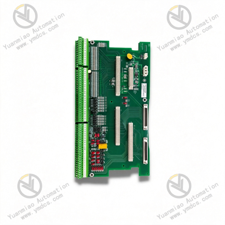
IS200TCASH1ACB is a dedicated core signal terminal board for the GE Mark VIe turbine control system. It acts as the front-end analog signal interface and shielding routing unit, serving as the critical mating transition hardware between the PCAA core analog module, BCAA/BCAB signal processing boards and TCAT terminal boards. The board mainly performs LVDT displacement sensor excitation signal output, field analog signal shielding termination, system control power distribution, and conditioning & routing of multiple process signals. It delivers stable front-end signal link support for valve position displacement monitoring, analog acquisition & regulation, and servo actuator control of gas turbines and steam turbines. Adopting OEM surface-mount technology and power-plant-grade anti-interference design, it adapts to complex electromagnetic environments during long-term uninterrupted unit operation. As an indispensable interface accessory board for the Mark VIe analog control system, it is widely deployed for new combined-cycle power plant matching, thermal power turbine unit projects, industrial power plant system integration and legacy spare part replacement.
Core Functions
This board implements five core functions: conditioning of system analog signal links, LVDT excitation drive, shield grounding termination, control power distribution, and cross-board signal routing. It outputs multiple standard 3.2kHz sinusoidal excitation signals to supply stable excitation power for unit valve LVDT displacement sensors. It sorts and distributes plant-wide valve position feedback signals, 4-20mA analog signals and process monitoring signals, and routes them sequentially to BCAA, BCAB analog processing boards and PCAA core acquisition modules. Meanwhile, it completes standardized grounding termination for all analog cable shielding layers to suppress field noise interference and line coupling interference, eliminating analog signal jitter, drift and distortion. In addition, it handles the access and distribution of 28V DC system control power, supplying stable operating power to downstream JGPA transition assemblies and signal link units, ensuring complete signal paths, pure signal quality and reliable operation of the entire analog acquisition and regulation system.
Compatible Systems
Fully compatible with the complete GE Mark VIe Speedtronic turbine control system, supporting simplex, dual redundant and TMR triple modular redundant control architectures for gas-steam combined cycle units, condensing steam turbine units and industrial drive turbine control systems. It seamlessly matches the PCAA multi-function analog module, BCAA/BCAB signal conditioning boards, TCAT extended terminal boards and JGPA power transition boards, complying with OEM backplane bus specifications, cabinet installation standards and underlying signal logic. Backward-compatible replacement is available for new and legacy systems without extensive modification of control programs and core wiring; signal paths can be restored via direct on-site installation. It fits all engineering scenarios including new unit commissioning, replacement of aged terminal boards, technical optimization of analog signal systems, and control system expansion & upgrade.
Application Scenarios
It is applied in large gas power plants, thermal combined-cycle power stations, cogeneration plants, oil & gas chemical power workshops and other facilities equipped with Mark VIe control systems. It serves the LVDT valve position monitoring loops for inlet valves, control valves, bypass valves and servo actuators of gas turbines and steam turbines, as well as analog acquisition loops for unit pressure, flow and temperature measurements. Designed for long-term operation under harsh cabinet conditions in power plants including high temperature, dust, mechanical vibration and strong electromagnetic interference, it undertakes front-end signal excitation, shielding protection, signal conditioning and power distribution to guarantee link stability for unit closed-loop valve regulation, process parameter monitoring and precise servo actuator control.
2. Technical Features
Dedicated LVDT Excitation Output for High-Accuracy Valve Position Monitoring
The board integrates 6 independent LVDT excitation output channels generating standard 3.2kHz sinusoidal excitation signals with a stable amplitude of 7.07 V RMS, precisely matching the operating requirements of various valve position LVDT displacement sensors on turbine units. The excitation signals feature pure waveform, stable frequency and low harmonic distortion, enabling accurate reproduction of tiny valve displacement variations. It ensures excellent linearity and precision of valve position feedback data, and provides reliable excitation support for unit PID closed-loop valve regulation, precise opening control and valve over-travel protection.
Multi-Channel Signal Conditioning & Routing with High System Integration
Equipped with multi-channel analog signal transition and routing circuits, it centrally organizes multiple LVDT feedback signals, 4-20mA analog signals and process monitoring signals and distributes them sequentially to downstream BCAA, BCAB and PCAA functional boards. It consolidates system analog signal paths, simplifies messy cabinet wiring and standardizes signal transmission routes, effectively reducing line crosstalk and wiring failure risks, and significantly improving the stability and maintainability of the overall analog control system.
Full-Range Shield Termination Design with Superior Anti-Interference Performance
Developed specifically for high electromagnetic environments in power plants, the board integrates dedicated signal shield termination and grounding conditioning circuits. It implements standardized grounding for all analog cable shielding layers to effectively isolate interference from variable frequency drives, high-voltage radiation, line surges and electrostatic coupling. It thoroughly resolves common field issues such as analog signal fluctuation, value drift, valve position oscillation and sampling distortion, maintaining clean and stable analog signals across the full signal chain.
Stable Power Distribution for Reliable Link Power Supply
Supports centralized access and precise distribution of 28V DC system control power. Power is conditioned and output via dedicated P5 and P4 connectors to deliver continuous stable operating power to JGPA transition assemblies and downstream signal link units. Built-in overvoltage, overcurrent and surge protection circuits resist transient grid fluctuations and line voltage shocks, preventing signal interruption, board malfunction and monitoring failure caused by abnormal power supply.
Standardized Interface Configuration for Strong Expansion Compatibility
Fitted with dual standard P1/P2 68-pin extended interfaces for stable connection with dedicated cables of TCAT extended terminal boards. It supports extension of multiple analog signals to meet expansion requirements for multi-channel valve position monitoring and process parameter acquisition. Interfaces adopt standardized definitions with wide compatibility for seamless matching with the full range of Mark VIe analog boards, supporting multiple system configurations including redundant architectures and TMR triple modular redundancy.
Industrial Ruggedized Construction with Excellent Environmental Tolerance
Constructed with imported industrial surface-mount components and reinforced PCB materials, processed with moisture-proof, dust-proof, anti-oxidation and anti-vibration treatments to deliver outstanding insulation and long-term stability. Capable of continuous operation under cabinet conditions with fluctuating temperature & humidity, mechanical vibration and dust accumulation in power plants; no circuit aging, connector oxidation or signal attenuation occurs during long-term operation to satisfy 24/7 unattended unit operation.
Passive Configuration-Free Operation for Convenient Maintenance & Replacement
As a passive signal routing terminal board, no control program configuration or parameter setting is required. It operates immediately after plugging in on-site for plug-and-play deployment. Standard dimensions and mounting structure fit OEM cabinet slots. Faulty legacy boards can be replaced directly without wiring modification or logic commissioning, greatly shortening maintenance downtime and reducing operation costs.
3. Specification Parameters
| Item | Parameter |
|---|---|
| Model | IS200TCASH1ACB |
| Manufacturer | GE General Electric |
| Product Series | Mark VIe Speedtronic Turbine Control System Terminal Board |
| Equipment Type | TCAS Analog Signal Shield Terminal Board, LVDT Excitation Signal Routing Board |
| Applicable Equipment | Gas Turbine, Steam Turbine, Industrial Turbine Power Equipment, Servo Control Valve Assemblies |
| Applicable System | GE Mark VIe Turbine Control System (Simplex/Dual/TMR Triple Modular Redundant Architecture) |
| Core Functions | LVDT excitation signal output, analog signal conditioning & routing, cable shield grounding termination, 28V control power distribution, signal transition for TCAT/PCAA/BCAA boards |
| LVDT Excitation Specifications | 6 excitation channels, 3.2kHz sine wave, standard amplitude 7.07 V RMS |
| Analog Output Range | 0~20mA, compatible with standard 4-20mA industrial analog signal loops |
| Excitation Voltage | 24VDC standard excitation matching voltage |
| Maximum Line Load | Maximum lead resistance 15Ω, suitable for long-distance field wiring |
| System Power Supply | 28V DC control power input |
| Interface Configuration | P5 power input connector, P4 power output connector, dual P1/P2 68-pin signal extended connectors |
| Matched Boards | PCAA core analog module, BCAA/BCAB signal conditioning boards, TCAT terminal board, JGPA transition board |
| Operating Frequency | Universal for 50Hz / 60Hz industrial power grids |
| Operating Temperature | 30℃~50℃ (Standard cabinet operating condition) |
| Storage Temperature | -40℃~+85℃ |
| Construction Material | Industrial surface-mount process, reinforced PCB, anti-oxidation gold-plated contacts |
| Overall Dimensions | 330.2mm × 178mm |
| Weight | Approx. 0.9kg |
| Electrical Features | Electromagnetic shielding, surge protection, line filtering, grounding conditioning, resistance to line crosstalk |
| O&M Characteristics | Passive configuration-free, plug-and-play, on-site replacement, no program commissioning, low failure rate |
| Product Characteristics | Clean signal transmission, stable excitation, organized signal routing, strong anti-interference, wide compatibility, easy maintenance, high long-term reliability |
4. Working Principle
4.1 System Power Access and Conditioned Distribution
After power-on, the board receives 28V DC system control power via the dedicated P5 connector. Built-in voltage regulation and filtering circuits suppress noise, stabilize voltage and absorb surges to filter transient grid fluctuations and electrical noise. Conditioned clean power is delivered steadily through the P4 connector to JGPA transition boards and downstream signal link units, providing reliable continuous power supply for the entire LVDT excitation loop and analog signal transmission paths to guarantee stable operation of front-end signal circuits.
4.2 Generation and Output of Standard LVDT Excitation Signals
The board integrates dedicated waveform generation and driver circuits to steadily generate 6 independent 3.2kHz, 7.07 V RMS sinusoidal excitation signals. These signals are routed via dedicated terminals to the primary windings of field-mounted LVDT displacement sensors. Constant-frequency and constant-amplitude excitation maintains optimal operating conditions for LVDT sensors. The induced voltage on the sensor secondary winding varies linearly with valve displacement to accurately feed back valve stroke data, providing standardized analog source signals for downstream data acquisition.
4.3 Conditioning and Shield Processing of Field Analog Signals
Field LVDT valve position feedback signals and 4-20mA process analog signals are fed into this terminal board and first processed by multi-stage hardware filtering circuits to eliminate line noise, electromagnetic interference, pulse jitter and other invalid signals. Simultaneously, standardized grounding termination is implemented uniformly for all signal cable shielding layers to completely eliminate coupling interference, electrostatic interference and radiation interference. Raw signals undergo waveform shaping and noise reduction to ensure distortion-free transmission.
4.4 Ordered Routing and Cross-Board Transmission of Multi-Channel Signals
Clean analog signals after filtering and shielding processing are sorted and distributed by internal conditioning circuits. LVDT valve position feedback signals and process analog signals are routed to BCAA and BCAB analog signal conditioning boards according to predefined system logic. After signal amplification, isolation and conversion, signals are transmitted to the PCAA core analog acquisition module for AD conversion and data collection. The P1 and P2 68-pin extended interfaces connect to TCAT terminal boards to realize extension of multiple signals and satisfy capacity expansion for multi-channel monitoring.
4.5 Full-Link Signal Protection and Stability Assurance
Relying on a three-layer protection framework consisting of shielded grounding, power regulation and signal filtering, the board continuously mitigates various electromagnetic disturbances generated by variable frequency drives, high-voltage equipment and unit start-stop operations in power plants, preventing analog signal drift, fluctuation and loss. Signal transmission paths are organized to reduce cross-line crosstalk and optimize signal quality of the whole analog control system, supporting precise valve regulation, stable process parameter monitoring and smooth servo actuator movement.
4.6 Passive Stable Operation to Support Redundant System Execution
This terminal board is passive signal adaptation hardware requiring no program configuration or parameter setup and operates reliably upon power-up. It fully supports simplex, dual redundant and TMR triple modular redundant architectures of Mark VIe. It is free of program execution faults and parameter disorder. It continuously supplies unified, synchronized and clean front-end analog signals to redundant control systems to guarantee signal consistency and synchronization, supporting fault-tolerant operation and stable regulation of turbine control systems.
5. Common Faults and Troubleshooting
5.1 Symptom: Valve position data drift, fluctuation and unstable feedback values
Possible Causes
① Poor board shield grounding; cable shielding layers not properly terminated, allowing electromagnetic interference to intrude into signal loops;
② Abnormal LVDT excitation channels with offset excitation frequency/amplitude leading to unstable sensor operation;
③ Oxidized board terminals and loose wiring causing poor signal contact;
④ Aging field wiring with degraded insulation resulting in signal crosstalk;
⑤ Dust accumulation and sustained high cabinet temperature leading to degraded performance of filtering circuits.
Solutions
Comprehensively inspect grounding of all analog cable shielding layers, re-terminate shielding wires and strengthen overall cabinet grounding. Measure LVDT excitation output frequency and amplitude to locate abnormal excitation circuits. Clean oxidation on board terminals and 68-pin interface contacts and fasten all wiring terminals. Replace aged damaged signal cables and separate strong and weak current wiring to eliminate crosstalk. Clean dust on the board and cabinet air ducts to improve heat dissipation. If data drift and fluctuation persist after verifying field wiring and sensors, aging of board filtering or excitation circuits is confirmed; replace with original IS200TCASH1ACB terminal board.
5.2 Symptom: Missing valve position feedback, interrupted LVDT signals on partial channels
Possible Causes
① Damaged excitation output circuits on corresponding channels with no excitation signal output;
② Loose channel terminals, broken cables or detached connectors;
③ Poor contact of P1/P2 extended interfaces leading to signal interruption;
④ Abnormal channels on downstream TCAT and PCAA boards resulting in signal reception failure;
⑤ Abnormal board power distribution with missing power supply for partial loops.
Solutions
Measure LVDT excitation output signals channel by channel to identify faulty channels. Inspect field wiring and connectors for the affected channels and repair broken circuits and loose connections. Remove, clean and re-seat 68-pin extended interface cables. Test power supply at P4/P5 connectors to troubleshoot power distribution faults. Check operating status of downstream TCAT and PCAA boards to rule out downstream equipment failures. If no signal output is detected after confirming field wiring, power supply and downstream hardware are normal, local channel damage on the board is confirmed; replace the spare part.
5.3 Symptom: Chaotic system analog signals and asynchronous multi-channel data
Possible Causes
① Abnormal internal signal routing circuits causing channel crosstalk and signal mixing;
② Confused cabinet grounding and multi-point grounding introducing interference potential differences;
③ Long-term vibration leading to poor internal soldering and abnormal circuit performance;
④ Failed power supply filtering with noise interfering with signal loops;
⑤ Incorrect wiring and mismatched interface definitions resulting in signal mutual interference.
Solutions
Reorganize the cabinet grounding system, implement unified single-point grounding to eliminate potential difference interference. Verify all signal wiring definitions, correct non-standard wiring and isolate individual channel loops. Test purity of input power supply and troubleshoot filtering circuit faults. Tighten board mounting screws and install cabinet vibration dampers to reduce shock impact. Clear accumulated dust and restore standard operating conditions. If multi-channel signal disorder remains after rectification, internal routing circuit failure of the board is confirmed; replace with original terminal board.
5.4 Symptom: Abnormal operation and unstable power supply of downstream JGPA and TCAT boards
Possible Causes
① Oxidation and looseness of P4/P5 power connectors causing poor power transmission;
② Aging board power distribution circuits and degraded voltage regulation/filtering leading to fluctuating output voltage;
③ Abnormal input 28V DC control power exceeding rated operating range;
④ Overloaded downstream loads triggering protective anomalies of board power loops;
⑤ Dust and moisture absorption reducing circuit insulation and causing power supply loop abnormalities.
Solutions
Measure system 28V DC input voltage to eliminate upstream power faults. Clean contact surfaces of P4 and P5 power connectors and tighten wiring terminals. Test stability of board output power and troubleshoot voltage regulation and filtering circuit defects. Inspect load conditions of downstream JGPA and TCAT boards to remove overload risks. Carry out dust removal and dehumidification maintenance to recover insulation performance. If downstream equipment still suffers unstable power supply after eliminating external power and load faults, damage to the board power distribution circuit is confirmed; replace the spare part.
5.5 Symptom: Degraded signal accuracy and increased system control deviation after long-term operation
Possible Causes
① Long-term high-temperature aging of board components leading to parameter offset in excitation and filtering circuits;
② Oxidized contacts and increased circuit impedance causing signal attenuation;
③ Long-term electromagnetic stress reducing circuit stability;
④ Excessive cabinet temperature and humidity accelerating performance degradation.
Solutions
Optimize cabinet temperature and humidity control to maintain rated operating conditions for the board. Thoroughly clean oxidation on all interfaces and terminals to reduce circuit impedance. Measure excitation signal accuracy and signal transmission linearity and compare against factory specifications. Optimize grounding and anti-interference measures to shield external electromagnetic impact. For boards with continuously degraded performance and control deviation that cannot be recovered via external rectification, replace with original IS200TCASH1ACB terminal board promptly to restore system signal precision and control stability.