Description
1. Product Overview
Part Number: IS200TDBTH6A, common revised versions IS200TDBTH6ACD / IS200TDBTH6ABC
Manufacturer: General Electric (GE). It is a dedicated split front-main-card & rear-terminal I/O backplane for the Speedtronic Mark VI / Mark VIe gas and steam turbine control system. Only factory surplus stock, refurbished used and redundant spare parts are available on the market, serving as the standard core wiring transition board for thermal combined-cycle units and chemical compressor turbine main control systems.
System Compatibility: It adopts a split architecture requiring matching Mark VI series front logic main cards. It natively supports simplex standalone operation and TMR Triple Modular Redundancy voting architecture. Three groups of high-density Euro connectors interface with the rack VME parallel backplane bus, bridging field on-site wiring between external field signals and rack main control units, realizing electrical isolation, line distribution, surge protection and signal forwarding.
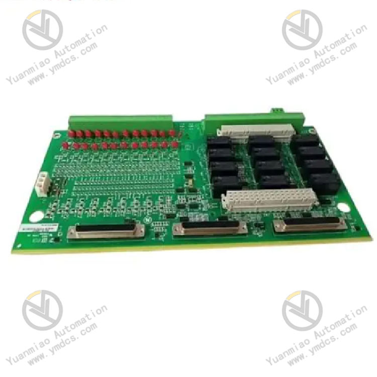
Product Definition: An integrated terminal backplane with
24 groups of isolated digital DI dry contact inputs + 12 Form-C relay DO outputs, acting as the bottom-layer wiring hub for hardwired signals of the Mark VI control system. It collects passive switch signals including circuit breaker status, local operation buttons, equipment fault feedback and limit switches. Meanwhile, it outputs trip commands, audible & visual alarms, interlock lockout and valve drive contact signals via onboard relays. Multi-stage lightning surge absorption, hardware filtering and loop current limiting protection are integrated to mitigate interference from long field cables to the main control system, making it the most widely used rear wiring substrate for IO loops of the Mark VI platform.
2. Six Core Hardware Functional Units
2.1 24-Channel Group-Isolated DI Dry Contact Input Acquisition Unit
24 digital input channels are divided into electrically isolated groups, with 24VDC power fed from the backplane side, compatible with 24V/48V/125VDC passive wet contact signals. Each channel is equipped with MOV varistors, filter diodes and RC snubber circuits, with 12V RMS hardware anti-AC interference capability per group and inter-group isolation voltage ≥2500VAC. It eliminates ground loop interference and induced noise in heavy EMI power plant environments to prevent unstable reading and false triggering. Onboard red LEDs correspond to each input channel; the indicator lights up upon valid signal access for intuitive troubleshooting of open/short field wiring faults.
2.2 12-Channel Onboard Relay DO Contact Output Unit
12 sets of original Panasonic Form-C SPDT relays form 12 independent passive output loops, with rated contact specifications: 3A@24VDC, 0.6A@125VDC, 3A@120/240VAC. The contacts can be directly wired to trip loops, alarm circuits, solenoid valves and intermediate relay coils. Surge suppression components are paralleled on each output path to absorb back EMF from inductive loads and avoid high-voltage reverse feed damaging signal chips on the front main card. All output channels are mutually isolated; short circuit on a single load will not disable the entire output array of the board.
2.3 Multi-Interface Backplane Bus Interconnection Unit
Three groups of DB high-density connectors on the upper side of the board connect to front rack processor main cards via dedicated flat cables for uploading DI acquisition data and downloading DO output instructions. Two terminal blocks TB1 and TB2 with 48 wiring terminals are reserved on the lower edge. All field cables terminate directly on the terminal blocks without secondary wiring inside the rack. Replacing front main cards will never disturb field primary wiring, drastically shortening maintenance outage duration.
2.4 Hardware Surge and Multi-Layer Protection Unit
A large array of metal oxide varistors, feedthrough filter capacitors and current-limiting fuse branches are laid out across the PCB to clamp and limit lightning surge, power-on inrush and accidental misconnection of high voltage from external field lines. Reverse-polarity protection circuitry is built into input ports; reversed wiring will not burn out the channel instantly, confining faults to a single channel and protecting the rack backplane and core processor modules.
2.5 Onboard Diagnostic and Loop Monitoring Unit
Besides channel input indicators, onboard hardware self-test points and bus communication monitoring circuits are integrated. The main control system periodically reads fault information including channel open circuit, line short circuit, relay adhesion and connector communication loss, with fault codes uploaded to the unit DCS and monitoring HMI. Single-channel software bypass is supported; maintenance on one field line only disables the corresponding point while other interlock and acquisition loops remain active without unit load reduction or shutdown.
2.6 Industrial Reinforced Anti-Vibration & Conformal Coating Unit
The double-sided gold-plated FR-4 PCB is fully coated with moisture, salt-fog and corrosion resistant conformal coating. Fanless passive heat dissipation relies on cabinet airflow. No adjustable potentiometers or aging-prone electrolytic capacitors are used. It withstands high temperature and dust accumulation inside sealed cabinets, long-term low-frequency vibration from turbine bases and humid coastal environments, enabling 24/7 unattended maintenance-free continuous operation.
3. Technical Specifications
3.1 Basic Hardware Specifications
| Item | Specification |
|---|
| Base Part Number | IS200TDBTH6A (ACD/ABC suffix indicates batch hardware revision) |
| Architecture | Split IO rear terminal board for Mark VI/VIe, no VME rack slot occupation |
| Channel Configuration | 24 isolated DI passive inputs + 12 SPDT relay DO outputs |
| Local Terminals | TB1 & TB2 barrier terminal blocks with total 48 connection points |
| Backplane Connection | 3 DB data connectors with dedicated cables to front main control cards |
| Onboard Logic Power | +5VDC supplied from rack backplane |
| Net Weight | Approx. 1.0kg |
| Dimension | 263mm × 138mm × 88mm |
| Origin | Original USA GE Manufacture |
3.2 Core Electrical Parameters
- DI Input: 24/48/125VDC passive dry contact compatible, input impedance>80kΩ, 2500VAC isolation between groups
- DO Relay Contacts: SPDT, rated load 3A@240VAC; 0.6A@125VDC; 3A@24VDC
- EMI Rejection: Hardware filter suppresses 12V RMS power frequency crosstalk
- Redundancy Mode: Simplex single-board operation; TMR triple redundancy requires 3 sets of terminal boards + matched front main cards
- Fault Detection: Open circuit, short circuit, overrange, communication loss and relay adhesion fault reporting supported
3.3 Environmental & Safety Compliance
- Operating Temperature: -30℃ ~ +65℃
- Storage & Transport Temperature: -40℃ ~ +85℃
- Humidity: 5%~95%RH non-condensing, free of corrosive gas and salt fog deposition
- Split front-rear architecture terminates all field wiring on the rear terminal board. Replacement of front main cards requires no rewiring of field cables, minimizing unplanned unit outage during emergency maintenance.
- Highly integrated all-in-one design consolidates 24 signal inputs and 12 relay drives on one single board, reducing cabinet hardware quantity and intermediate terminal fault points, fully native compatible with Mark VI system with no third-party drop-in alternatives.
- Multi-layer hardware protection including reverse polarity prevention, surge clamping, group isolation and per-channel current limiting effectively avoids hardware damage caused by field miswiring, lightning induced voltage and cable short circuits.
- Seamless compatibility with both simplex control and TMR triple redundant safety architecture. 2-out-of-3 voting eliminates false trip and protection refusal risks from single-point board or line faults, complying with SIL2 functional safety interlock standards for large power generation units.
- Visual per-channel LED indication allows on-site cable continuity and signal verification without configuration software, simplifying on-site troubleshooting.
- Excellent backward compatibility with legacy in-service GE 6FA/9FA gas and steam turbine units. Spare replacement reuses original terminal wiring and system configuration with no control program modification needed.
1. Thermal Power GE Combined-Cycle Gas & Steam Turbine Mark VI Main Control System
Exhaust temperature switch signals, combustion system limit feedback, circuit breaker status, emergency shutdown pushbuttons and local start/stop commands are wired to DI channels. DO outputs drive fire suppression solenoids, turbine trip interlocks, local audible/visual alarms and lube oil system solenoid valves, forming the core wiring backplane for turbine primary protection loops.
2. Petrochemical Large Process Compressor Control Systems
Shaft protection, anti-surge interlock and local operator signals for cracking gas and recycle hydrogen compressors are collected and forwarded. Conformal coating resists dust and corrosive atmosphere in chemical plants to extend service life.
3. Large & Medium Hydropower Unit Governor and Turbine Main Control System
Gate limit switches, overspeed protection contacts, cooling fan status and synchronizer interlock signals are relayed. Conformal coating mitigates terminal oxidation and signal drift caused by humid mist in hydropower stations.
4. Captive Power Plants & Waste Heat Power Generation Steam Turbine Control Systems
TSI switch signals, emergency trip loops and auxiliary equipment interlock signals act as the hardwired interface between plant-wide DCS and local turbine control units.
![]()