Description
1. Product Overview
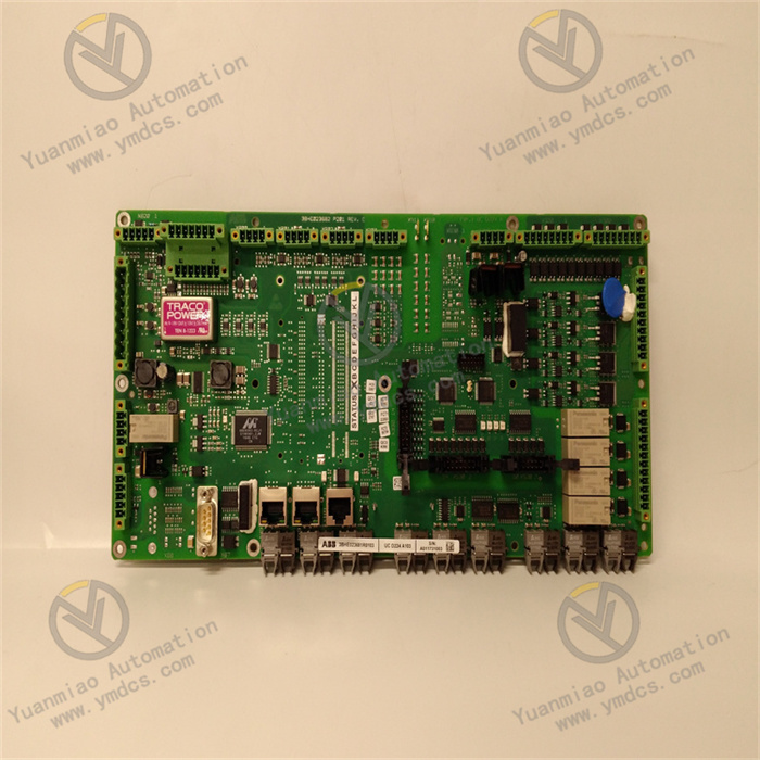
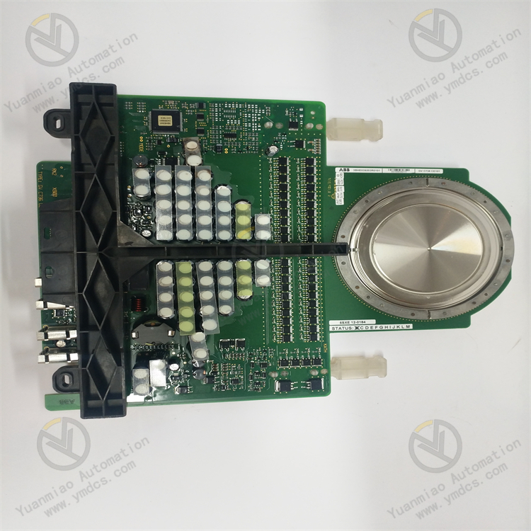
ABB 3BHB007438R0001 is an IGCT drive signal acquisition and status monitoring interface board for high-voltage frequency converters, HVDC converters and high-power converter systems. It is perfectly matched with ABB 5SHY series IGCT power modules, serving as the core intermediate board for drive pulse transmission, fault feedback and status signal forwarding between the main control unit and IGCT power sub-modules.This board transmits optical fiber trigger commands from the upper main controller, converts optical signals into gate drive levels for IGCTs, uploads real-time switching feedback signals of power devices, and latches hardware faults such as overcurrent, overvoltage and gate drive abnormality. Adopting full-channel optoelectrical isolation and wide-temperature industrial components without wearing mechanical parts, it is manufactured in Switzerland with CE, UL, IEC power equipment and ABS marine certifications, featuring excellent anti-interference performance against harmonics in high-power converter cabinets. It is widely used for spare part replacement and system expansion of high-voltage inverters, wind power converters, energy storage grid-tie converters, metallurgical rolling mill drives, SVG reactive power compensation devices and marine electric propulsion converters.
2. Hardware Structure and Composition
2.1 Optical Fiber Drive Signal Transceiver & Conversion Unit
Multiple independent multi-mode fiber transmit and receive ports are integrated on the board. Downward optical fiber on/off commands from the main control board are converted into electrical drive signals for IGCT gate units. Upward feedback signals of actual IGCT conduction are collected and sent to the on-board logic chip for timing verification to prevent false triggering and pulse loss.Each channel is equipped with optical power detection to identify fiber breakage, connector contamination and signal attenuation. Single-channel failure will not occupy bus resources or affect monitoring of other power branches.
2.2 IGCT Fault Signal Acquisition & Latching Unit
Built-in hardware latch circuits capture hard faults including gate overcurrent, reverse breakdown, drive power undervoltage and device overheating. Fault status is latched permanently until a reset command is issued by the upper main controller, avoiding missing transient faults that may cause severe equipment damage.All fault signals are protected by TVS surge suppression and electrical isolation to prevent high-voltage surges from the power side from damaging the upper main control board.
2.3 Inter-Board Bus Data Interaction Unit
A standard European double-row gold-plated backplane connector is installed on the rear of the board. After being inserted into the rack slot, it connects to the internal parallel bus to upload channel status, fault codes, optical link conditions and power supply sampling data, while receiving enable, reset, channel masking and parameter calibration instructions from the main controller.Multi-stage filtering and ESD protection are embedded in the bus circuit to resist high-frequency electromagnetic radiation from switching power devices inside the cabinet and prevent data corruption and packet loss.
2.4 Auxiliary Power Monitoring & Multi-Level Hardware Protection Unit
On-board multi-channel voltage sampling circuits monitor the working voltage of IGCT drive power and the board itself. Protection will be activated immediately to cut off drive pulses in case of undervoltage, overvoltage or short-circuit to avoid IGCT breakdown caused by abnormal power supply.The board is powered by 24VDC auxiliary power from the converter rack, with an isolated DC-DC module converting input voltage into multiple regulated power supplies for optical transceivers, logic circuits and signal acquisition. Five-level protection including reverse polarity, overcurrent, short-circuit and lightning surge is implemented.
2.5 Front Panel Indication & Global Diagnosis Unit
Dual-color LED indicators are arranged on the front panel: PWR (power), COM (communication), LINK (fiber link), FAULT (hardware fault). Steady PWR indicates normal power supply; blinking COM means normal bus communication; flashing LINK synchronizes with fiber pulses to show valid signal transmission; steady FAULT denotes channel failure, power anomaly or IGCT fault.Complete fault logs, channel numbers and fault types can be read and exported via ABB ConMaker and DriveWindow commissioning software for troubleshooting traceability.
2.6 Standard Rack-Mounted Modular PCB Assembly Unit
Flame-retardant V0 high-temperature resistant PCB with reinforced component soldering, designed as a single-slot board for standard 19-inch converter rack installation. Gold-plated backplane pins resist oxidation and corrosion to ensure stable contact under long-term vibration. A grounding pad is reserved for equipotential shielding with the cabinet frame, requiring no consumable maintenance during service life.
3. Technical Specifications
3.1 Signal & Operation Performance
Part Number: 3BHB007438R0001Compatible Devices: ABB 5SHY series IGCT integrated gate commutated thyristorsCommunication Mode: Up/down fiber serial communication + rack backplane parallel busFiber Type: Industrial multi-mode fiber with standard HFBR optical transceiversFault Detection Items: Fiber break, drive power abnormality, IGCT gate overcurrent, missing feedback pulse, timing errorFault Storage: Hardware latch, temporary fault marking retained after power offResponse Delay: ≤1μs to meet high-speed protection timing of high-power convertersIsolation Withstand Voltage: ≥2500VDC between fiber port, power signal circuit and main control bus
3.2 Electrical Parameters
Rated Input Power: 24VDC (18~36VDC allowable range)Typical Power Consumption: ≤4.5WOutput Gate Drive Level: Standard voltage level matching ABB IGCT driversHot Swap: Hot plugging on rack is not supportedSupport Software: ABB ConMaker, DriveWindow, PCS800 Configuration PlatformCountry of Origin: Switzerland
3.3 Environmental Specifications
Operating Temperature: -25℃ ~ +70℃Storage & Transport Temperature: -40℃ ~ +85℃Relative Humidity: 5%~95%RH non-condensing, no corrosive gasIngress Protection: IP20 (for installation inside sealed converter cabinets only)Pollution Degree: Class 2EMC Standard: IEC 61000-4 Class A industrial anti-interference levelVibration Compliance: IEC 60068-2-6 for continuous vibration in rolling mills and marine equipmentMax Operating Altitude: ≤2000m
3.4 Mechanical Dimensions
Mounting Method: Vertical insertion and fixing into standard converter rack slotsOverall Size: L235mm × W120mm × T35mmNet Weight: Approx. 0.42kgBase Material: High-temperature flame-retardant PCB, gold-plated backplane contact pins
Full optoelectrical isolation eliminates EMI from high-voltage power loops
Fiber serves as the only transmission medium between high-voltage power circuits and low-voltage control systems, blocking harmonic noise, ground potential difference and surge interference to protect the main control board from high-voltage damage.
Hardware-based fault latch and ultra-fast protection prevent irreversible IGCT damage
Fault judgment relies on hardware logic instead of software programs. Protection and pulse locking remain effective even if the main controller crashes or bus communication is lost, avoiding short circuit and burnout of power units.
Parallel independent multi-channel monitoring ensures partial-load operation upon single branch fault
Each fiber channel operates independently. Fault on one channel only disables the corresponding drive output, and the rest of the converter can run under derated mode without full shutdown, applicable to non-interruptible loads such as wind power and grid-connected equipment.
Standard rack compatibility enables direct plug-and-play replacement for legacy equipment
Unified slot size, pin definition and bus protocol allow direct in-situ replacement of damaged boards without rewiring or program modification. System operation can be restored after parameter download to minimize downtime.
Wide-temperature industrial hardware adapts to harsh multi-scenario conditions
Industrial-grade components support stable operation in low-temperature outdoor cabinets, high-temperature enclosed converter rooms and salt-spray marine environments with long service life matching power equipment’s 10+ year design lifespan.
Power Grid Industry: SVG static var compensators, high-voltage direct-drive inverters, flexible DC converter valve power unit monitoring.New Energy Industry: Onshore/offshore wind converters, centralized PV inverters, energy storage grid-tie converter drive and fault protection.Metallurgy Industry: Main drive high-voltage inverters for steel rolling lines and arc furnace power supply systems.Marine & Offshore Engineering: Main propulsion converters for vessels and power supply equipment on offshore platforms.Mining & Heavy Industry: High-voltage drive inverters for mine hoists and large belt conveyors.
![]()