Description
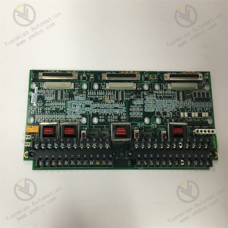
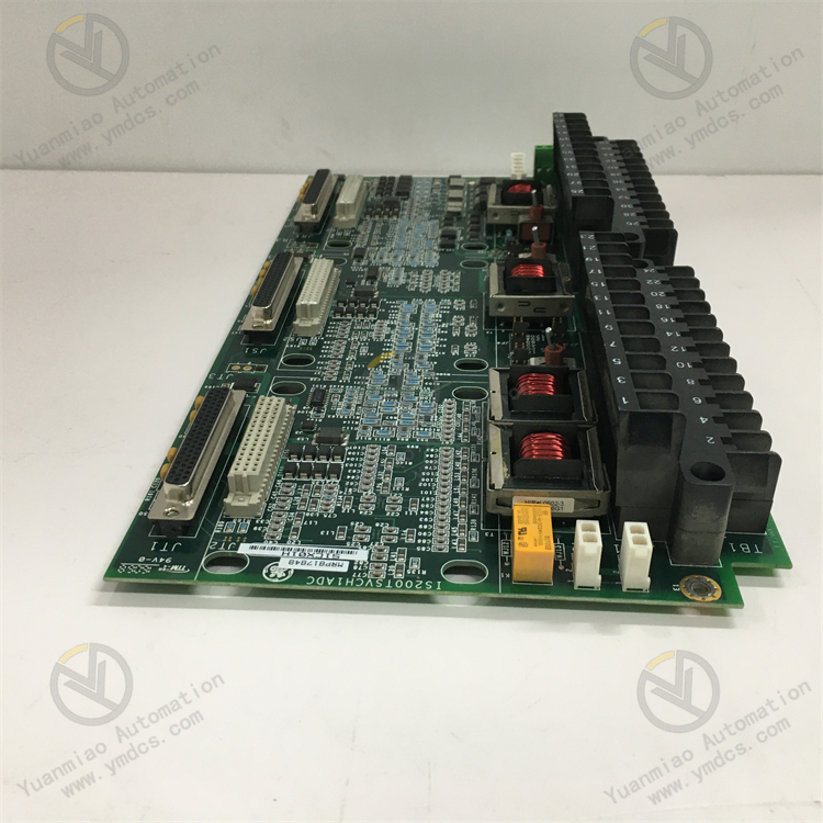
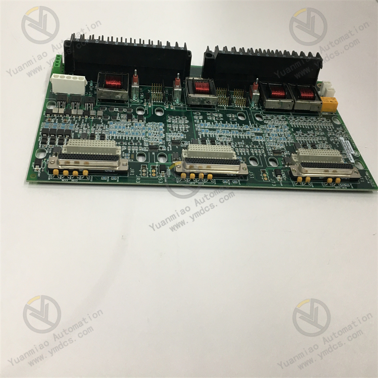
GE IS200TSVCH1ADC
Functional Features
- Signal Processing and Control
- May be used in turbine systems to process analog or digital signals such as temperature, rotational speed, and valve position.
- Supports signal acquisition, conditioning (e.g., amplification, filtering), and analog-to-digital/digital-to-analog conversion (A/D or D/A conversion).
- May integrate PID control algorithms to achieve closed-loop control of actuators (e.g., control valves, servo motors).
- Application Scenarios
- Core Applications: Control systems for wind power, gas turbines, and steam turbines as part of the Mark VI system.
- Functional Positioning: Likely responsible for critical tasks such as turbine speed regulation, temperature monitoring, and valve servo control to ensure stable unit operation.
- Interfaces and Communication
- May be equipped with analog input/output channels (e.g., 4-20mA, 0-10V signals) and digital interfaces.
- Supports communication protocols such as Ethernet, Modbus, and RS-485 for communication with host computers or other modules (e.g., main control modules, I/O modules).
- Reliability Design
- Industrial Environment Adaptability: Wide temperature range (-40°C~70°C), vibration resistance, and electromagnetic interference (EMI) immunity.
- Redundancy Design: May support simplex or redundant configurations (e.g., Triple Modular Redundancy TMR) to enhance system fault tolerance.
Technical Parameters
I. Basic Parameters
| Parameter | Possible Range/Description |
|---|---|
| Series | GE Mark VI Turbine Control System |
| Module Type | Possibly a sensor interface module or signal conditioning module (推测 based on "TSVC" in the model, related to sensor control) |
| Power Supply | Typically 24 VDC or 125 VDC (subject to specific applications) |
| Dimensions | Standard industrial module size (e.g., compliant with IEEE standards for cabinet installation) |
| Operating Temperature | -40°C ~ +70°C (adaptable to harsh industrial environments) |
| Protection Level | IP20 (indoor installation, protected against solid foreign objects) |
II. Signal I/O Parameters
- Input Channels
- Analog inputs (e.g., voltage, current signals such as 4-20 mA, 0-10 V).
- Digital inputs (e.g., switch signals, TTL/CMOS levels).
- Quantity: 8 or 16 channels (common configuration for similar modules).
- Signal Types:
- Resolution: 12-bit or 16-bit (depending on accuracy requirements).
- Sampling Rate: Typically ≥100 Hz (real-time sensor data acquisition).
- Output Channels
- Analog outputs (e.g., 4-20 mA current signals to drive actuators).
- Digital outputs (relay contacts or transistor outputs).
- Quantity: Possibly 4 or 8 channels (for control signal output).
- Signal Types:
- Load Capacity: e.g., relay output contact capacity 2A@250VAC.
- Communication Interfaces
- Ethernet (e.g., Modbus TCP, EtherNet/IP).
- Serial communication (e.g., RS-485, Modbus RTU).
- Supported Protocols:
- Interface Types: RJ45 (Ethernet), DB9 (serial port), or proprietary connectors.
Working Principle
- Analog Signal Acquisition and Conditioning
- May include anti-aliasing filters (to avoid sampling distortion) and signal amplification circuits (to match ADC input ranges).
- Example: The AC voltage signal output by a turbine speed sensor (e.g., a reluctance probe) must first be processed by a signal conditioning circuit.
- Signal Input: The module receives analog signals (e.g., 4-20mA current signals, 0-10V voltage signals, thermocouple/thermal resistance temperature signals) from sensors via front-end interfaces.
- Signal Conditioning: Preprocesses input signals through filtering, amplification, and isolation to eliminate noise and ensure signal accuracy.
- Analog-to-Digital Conversion (ADC)
- Core Function: Converts analog signals to digital signals (binary codes) via a built-in analog-to-digital converter (ADC chip).
- Key Parameters: Sampling rate, resolution (e.g., 16-bit, 24-bit), and conversion accuracy determine signal processing precision.
- Multi-Channel Processing: The module may support multi-channel synchronous sampling to ensure simultaneous acquisition of multiple analog quantities (e.g., temperature and pressure at different measurement points of a turbine) and avoid timing errors.
- Digital Signal Processing and Communication
- May support redundant communication (e.g., dual-bus architecture) to enhance system reliability.
- Data Processing: Calibrates, linearizes, and converts digital signals into engineering quantities (e.g., converting voltage values to actual temperature values), storing them in module registers.
- Communication Output: Transmits processed digital signals to the main controller (e.g., CPU module) or other system components via bus interfaces (e.g., GE's Speedtronic bus, Ethernet, serial communication).
- Closed-Loop Control and Protection Logic (if control functions are involved)
- Speed closed-loop control: Calculates control quantities via PID algorithms based on acquired speed signals and outputs them to actuators (e.g., fuel control valves).
- Protection logic: Triggers emergency shutdown or alarm signals via hardware circuits (e.g., relays) or communication interfaces when abnormal signals (e.g., overspeed, overheating) are detected.
- If the module has output control functions (e.g., related to "control" in TSVC), it may participate in:
- Power Supply and Self-Test
- Power Management: The module is typically powered by a system-provided DC supply (e.g., 24VDC or 125VDC), with internal power circuits converting it to voltages required by chips, and featuring overvoltage and undervoltage protection.
- Self-Test Function: Built-in diagnostic circuits regularly check ADC accuracy, communication links, and power status. If faults (e.g., chip anomalies, signal overruns) are detected, fault codes are reported via indicator lights or communication interfaces.
Common Faults and Solutions for GE IS200TSVCH1ADC Module
I. Communication Faults
- Symptoms:
- The module cannot communicate with the host computer (e.g., PLC, DCS system), or data transmission is abnormal.
- Communication indicator lights (e.g., RX/TX lights) are off or flashing abnormally.
- Possible Causes:
- Communication cable issues: Damaged cables, poor connections, or incorrect wiring (e.g., loose terminals, reverse polarity).
- Incorrect communication parameter settings: Mismatched baud rate, parity, data bits, stop bits, or slave address with the host computer.
- Interface hardware faults: Damaged communication chips, oxidized interface pins, or physical damage (e.g., loose interfaces due to frequent plugging/unplugging).
- Electromagnetic interference: Unshielded communication cables or proximity to strong electromagnetic devices (e.g., motors, inverters).
- Solutions:
- Check cables and wiring:
- Test cable continuity with a multimeter and replace damaged cables.
- Re-plug terminals to ensure secure connections and verify wiring diagrams (e.g., distinguish A/B lines for RS-485).
- Reconfigure communication parameters:
- Use GE proprietary software (e.g., Proficy Machine Edition) or debugging tools to confirm parameter consistency between the module and host computer.
- Clean or replace interfaces:
- Wipe interface pins with isopropyl alcohol to remove oxidation; professional repair or module replacement is required for bent or broken pins.
- Anti-interference measures:
- Replace with shielded twisted-pair cables, ensure they are away from strong electromagnetic sources, and install matching terminating resistors (e.g., 120Ω) at communication terminals as needed.
II. Input/Output (I/O) Faults
- Symptoms:
- Abnormal analog input (AI) signals (e.g., fluctuating values, large deviations).
- No response from digital output (DO) (e.g., relays not activating, indicator lights off).
- Possible Causes:
- Abnormal analog inputs:
- Sensor faults (e.g., damaged transmitters, insufficient power supply).
- Poor cable shielding causing signal distortion due to interference.
- Damaged module channels or incorrect range settings (e.g., not matching sensor output ranges).
- Abnormal digital outputs:
- Actuator (e.g., relay, solenoid valve) power faults or load short circuits.
- Hardware damage to module output channels (e.g., transistor breakdown, relay contact wear).
- Control logic errors (e.g., programs not triggering outputs or safety interlocks not released).
- Solutions:
- Troubleshoot analog inputs:
- Measure sensor output signals with a multimeter and replace faulty sensors.
- Check grounding of cable shielding layers to avoid multi-point grounding; replace shielded cables.
- Confirm input ranges (e.g., 4-20mA, 0-10V) match sensors via module configuration software and calibrate channels (if self-calibration is supported).
- Troubleshoot digital outputs:
- Check actuator power supplies and test output terminals for voltage/current with a multimeter.
- Test with spare channels; if working, the original channel is damaged and requires repair or module replacement.
- Review control program logic to ensure output conditions are met (e.g., interlocks released, trigger signals active).
III. Power Supply Faults
- Symptoms:
- Module power indicator light is off or flashes frequently.
- Unstable module operation, random restarts, or crashes.
- Possible Causes:
- Abnormal supply voltage: Input voltage outside the module's allowable range (e.g., rated 24VDC but actual voltage fluctuates excessively).
- Poor power terminal connections: Loose terminals, oxidation, or loose cable connections.
- Internal power circuit faults: Bulging filter capacitors, damaged power chips, etc.
- Solutions:
- Measure supply voltage:
- Use a multimeter to confirm input voltage is within the module's rated range (e.g., IS200TSVCH1ADC may support 18-32VDC). Stabilize the voltage source or install a voltage regulator.
- Check power wiring:
- Tighten power terminals, replace oxidized cable ends, and ensure reliable grounding.
- Replace module or repair:
- For internal power faults, contact GE authorized service providers to replace the module or repair the circuit board.
IV. Temperature or Environmental Faults
- Symptoms:
- Module overheating leads to performance degradation or shutdown, with alarm indicators activated.
- Abnormal operation in extreme temperatures (e.g., high or low temperatures).
- Possible Causes:
- Poor heat dissipation: Inadequate ventilation at the installation location or severe dust accumulation affecting heat dissipation.
- Exceeding environmental temperature limits: Operating temperature beyond the module's specified range (e.g., GE modules typically support -40°C~70°C, but long-term high temperatures may accelerate component aging).
- Solutions:
- Improve heat dissipation:
- Ensure vertical module installation with sufficient spacing (e.g., ≥25mm) from adjacent devices.
- Regularly clean module surfaces and cabinet interiors, and install fans or air conditioners to control ambient temperature.
- Avoid extreme environments:
- If ambient temperature consistently approaches limits, consider installing thermal insulation or relocating the module to a temperature-controlled area of the control cabinet.
V. Hardware Faults (Non-Volatile Faults)
- Symptoms:
- Module initialization fails, with persistent error codes (e.g., Error 0x03).
- Internal memory faults (e.g., program loss, parameter saving failures).
- Possible Causes:
- EEPROM or Flash memory damage: Aging of memory chips due to long-term operation or data corruption from sudden power outages.
- FPGA/ASIC chip faults: Hardware damage to logic chips, typically caused by overvoltage, overcurrent, or electrostatic discharge.
- Solutions:
- Restore factory settings or upgrade firmware:
- Use GE software to attempt restoring default configurations or updating module firmware (exercise caution to avoid data loss).
- Replace module:
- Memory or chip-level faults are generally not repairable on-site; replace with a new module and reconfigure parameters.