Description
GE IS420UCSBH3A
Functional Features
- High-Speed Processing Capability: Equipped with a 1200 MHz Intel EP80579 microprocessor, it can quickly handle various control tasks and data, providing strong computational support for real-time, high-speed, and reliable operations to meet the requirements of fast response and precise control in industrial automation.
- Multiple Communication Interfaces: Features various communication ports such as Ethernet, RS-232, and RS-485, enabling convenient data interaction and communication with other devices to achieve system integration and expansion.
- Flexible I/O Configuration: Supports multiple I/O modules, including digital input/output modules, analog input/output modules, and serial communication modules. It can flexibly configure input/output signals according to different application scenarios and control needs to achieve precise control of various industrial devices.
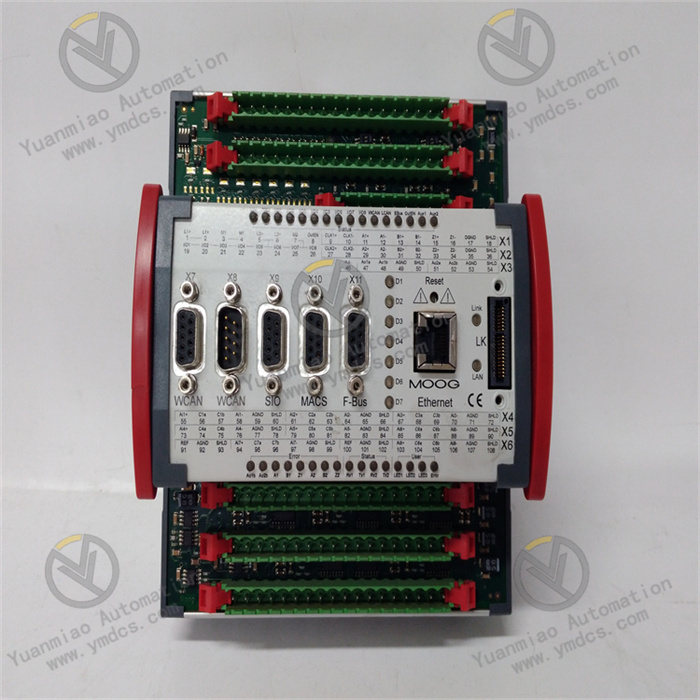
- Status Indication Function: The front panel is equipped with multiple LED indicators to display the controller's working status, such as whether internal components are overheated, the status of the recovery process, whether the controller is selected, and whether it is running online. This helps operators quickly understand the device's status for troubleshooting and maintenance.
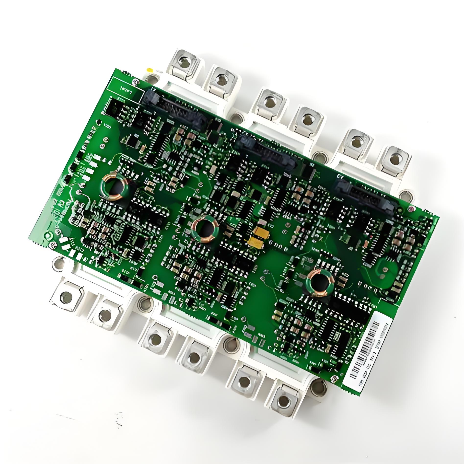
- Rugged and Durable Design: With a compact design (6.4 inches × 8.1 inches × 1.4 inches) and a weight of approximately 2.9 pounds, it is easy to install in control cabinets or on DIN rails. Its materials and structure can adapt to various industrial environments, operating stably within a temperature range of 0°C to 65°C, with high reliability and stability.
Technical Parameters
- Processor: Intel EP80579, 1200 MHz.
- Memory: Typically 1GB RAM and 2GB flash memory.
- Input Voltage: 24/28 VDC.
- Communication Ports: Ethernet, RS-232, RS-485, etc.
- I/O Modules: Supports multiple modules such as digital input/output, analog input/output, and serial communication.
- Dimensions: H 6.4 inches × W 8.1 inches × D 1.4 inches.
- Weight: Approximately 2.9 pounds.
- Operating Temperature: 0°C – 65°C.
- Wire Gauge: 28–16 AWG.
Operation Guide
Installation: Select an appropriate installation location according to the device installation manual to ensure the environment meets the controller's operating requirements (e.g., temperature, humidity). Firmly install the controller in a control cabinet or on a DIN rail, and connect power cables, communication cables, and I/O signal lines according to the wiring diagram to ensure secure connections and avoid looseness or poor contact.Configuration: Use dedicated programming software or a host computer control system to configure parameters and program the controller. Set communication parameters (e.g., IP address, baud rate) to enable normal communication with other devices. Configure the types of I/O modules, channel parameters, and corresponding control logic and algorithms according to specific control tasks.
Debugging: Perform system debugging before formal operation. Check if the controller's power supply is normal and if all indicator lights display correctly. Send test signals or simulate actual working conditions to verify the correctness of I/O module inputs/outputs, the normality of communication, and whether the control logic meets design requirements. Investigate and correct issues promptly if they arise.
Operation and Monitoring: Keep the controller running during industrial production and monitor its status in real time. Observe whether the controller is operating normally and whether there are fault alarms through the host computer monitoring system or the controller's own status indicator lights. Regularly check the controller's temperature, fan operation, etc., to ensure it operates in good condition.
Maintenance and Care: Regularly clean dust and debris from the controller's surface to maintain good heat dissipation. According to the device maintenance manual, periodically inspect the connections of power cables, communication cables, and I/O signal lines, and tighten them promptly if loose. Regularly upgrade the controller's software and maintain its hardware as recommended by the manufacturer based on actual usage to ensure its performance and functionality remain advanced and stable. In case of faults, first refer to the controller's fault code manual and instructions for preliminary diagnosis and troubleshooting. Simple faults (e.g., replacing damaged I/O modules or repairing communication lines) can be handled independently; for complex faults, contact GE technical support or professional maintenance personnel promptly.

How to Troubleshoot GE IS420UCSBH3A?
When troubleshooting the GE IS420UCSBH3A, follow these systematic steps:I. Preliminary Checks (Quickly Locate Obvious Issues)
Power Supply Check
- Confirm that the input voltage is normal (24/28 VDC). Use a multimeter to measure the voltage at the power terminals, with fluctuations within ±10% of the specified value.
- Check if the power indicator light (usually green) is on. If not, inspect the fuse, power module, and wiring connections.
Hardware Connection Check
- Ensure all I/O modules, communication cables, and power cables are securely inserted without looseness or oxidation.
- Examine the LED status indicators on the controller's front panel (e.g., RUN, FAULT, COMMS) and refer to the user manual to determine the fault type (e.g., a constant FAULT light indicates a system error).
Environmental Check
- Verify that the operating temperature (0°C–65°C) and humidity are within specified ranges. Check if the cooling fan is operating normally to prevent the controller from shutting down due to overheating.
II. System-Level Troubleshooting (Layered Diagnosis)
1. Communication Faults
- Ethernet Communication:
- Test the network connection to the controller using the ping command. If disconnected, check IP address configuration, switch ports, and network cables.
- Use diagnostic software (e.g., GE Proficy Machine Edition) to view communication status logs and analyze packet loss or timeout errors.
- Serial Communication (RS-232/RS-485):
- Ensure baud rate, parity bit, and other parameters match the peripheral devices.
- Test physical layer connectivity using a serial debugging tool (e.g., Putty).
2. I/O Module Faults
- Use the controller's diagnostic functions or host computer software to check the status of I/O modules (e.g., whether input values change or outputs respond).
- Replace suspected I/O modules (note: power off before operation) and observe if the fault transfers.
- Check if the module fuses are blown, especially for analog input/output modules.
3. Software and Configuration Faults
- Inspect program logic for infinite loops or conditional errors, which can be verified by online monitoring of variable values.
- Compare the current configuration with backup files to confirm if parameters have been accidentally modified (e.g., I/O address mapping, communication protocol settings).
- Try restarting the controller (press the RESET button or power cycle) to rule out temporary software glitches.
4. Processor and Memory Faults
- If the controller reboots frequently or becomes unresponsive, it may indicate insufficient memory or processor overheating. Check memory usage in system logs.
- Use diagnostic tools to read the processor temperature. If it exceeds 65°C, inspect the cooling channels for blockages.
III. Utilize Diagnostic Tools and Resources
LED Indicator Diagnosis
- Refer to the LED status code descriptions in the user manual (e.g.,
- FAULT light flashing: self-test failure or firmware error.
- COMMS light off: communication interruption.
Dedicated Diagnostic Software
- Use GE-provided software such as Proficy Machine Edition or Mark VIe Control Builder to read system event logs and fault codes.
- Monitor key variables (e.g., I/O values, processor load) online through the software to locate anomalies.
Hardware Testing
- Use the substitution method to replace suspected components one by one (e.g., power modules, I/O cards) to narrow down the fault scope.
- Perform loopback tests on communication ports (e.g., shorting RS-485 A/B lines) to verify physical layer integrity.
IV. Fault Handling and Documentation
Emergency Handling
- In case of severe faults such as module smoking or unusual odors, power off immediately and isolate the device to prevent fault escalation.
- For critical faults affecting production, switch to a standby controller (if the system supports redundant configuration).
Documentation and Reporting
- Record the fault occurrence time, symptoms, related variable values, and operation history.
- Save system logs and error codes, and provide detailed information (e.g., model, serial number, firmware version) when submitting to GE technical support.
V. Preventive Measures
Regular Maintenance
- Clean the controller's cooling vents quarterly and check fan operation.
- Conduct functional tests on I/O modules annually and replace aged cables.
Firmware Upgrades
- Update the controller's firmware to the latest version promptly to fix known vulnerabilities and compatibility issues.
Configuration Backups
- Backup to external storage immediately after modifying programs or configurations to facilitate fault recovery.