Description
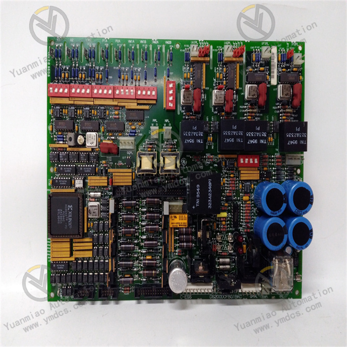
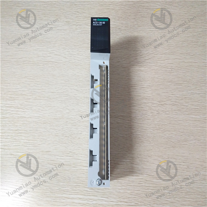
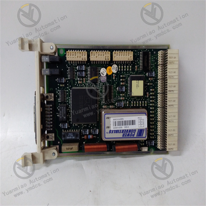
B&R 7DO138.70
I. Overview
The 7DO138.70 module features high reliability, strong driving capability, and good anti-interference performance. It can adapt to the complex electromagnetic environment and harsh working conditions of industrial sites, and is widely used in automation systems in many industries such as machinery manufacturing, automobile production, logistics and warehousing, and process control, providing strong support for the automated control of production processes.
II. Technical Parameters
Output signal type: Supports relay output, which is a common output method in industrial control. It has the characteristics of strong electrical isolation capability and a wide applicable voltage range, and can be adapted to different types of loads (such as AC or DC loads).
Rated load capacity: The rated load current of each relay output channel is usually large (specific values are subject to the product manual). For example, it can drive AC 250V/5A or DC 30V/5A loads, which can meet the driving needs of most industrial actuators, such as small motors, solenoid valves, indicator lights, etc.
Electrical isolation: Electrical isolation design is adopted between each output channel and between the channels and the backplane bus. The isolation voltage can generally reach more than 2500V AC, which effectively prevents external high voltage or interference signals from affecting the control system through the module, improving the safety and stability of the system.
Response time: The action response time of relay output is in the millisecond range (specific values refer to the product manual), which can quickly respond to the instructions of the control system, ensuring that the actuator acts in a timely manner and meeting the real-time requirements of general industrial control.
Power supply requirements: Usually powered by the I/O rack or a dedicated power module where it is located. The typical supply voltage is 24V DC, with low power consumption, which has little impact on the load of the system power supply and is convenient for system integration.
Environmental adaptability:
- Operating temperature: Generally, it can work stably within the range of 0°C - 60°C and can adapt to temperature fluctuations in industrial sites.
- Relative humidity: It can operate normally in a relative humidity environment of 5% - 95% (non-condensing) and can cope with humid production environments.
- Vibration and shock resistance: It meets the relevant standards of industrial equipment, has certain vibration and shock resistance capabilities, and can work reliably in occasions with slight vibrations (such as near machine tools and production lines).
III. Functional Characteristics
Reliable electrical isolation: Adopting multiple electrical isolation designs, it can not only effectively isolate the electrical connection between external loads and the control system, prevent the transmission of interference signals, but also protect the module itself and the control system from damage caused by external overvoltage and overcurrent, improving the anti-interference ability and operational reliability of the system.
Status indication function: The module is equipped with LED status indicators for each output channel. When the channel output signal is "ON", the corresponding indicator light is on; when it is "OFF", the indicator light is off. Operators can intuitively understand the working status of each channel through the indicator lights, which is convenient for system debugging, operation monitoring, and fault troubleshooting.
Diagnostic and protection functions: It has certain self-diagnostic and protection capabilities, and can monitor fault conditions such as overload and short circuit of output channels. When a channel has an overload or short circuit, the module will promptly cut off the output of that channel and upload the fault information to the control system through the communication bus to avoid the expansion of the fault, protect the safety of the module and external equipment, and facilitate maintenance personnel to quickly locate the fault point.
Flexible installation and integration: It adopts a standardized guide rail installation method, which is convenient to install. It can form a compact automation control system together with other B&R I/O modules, PLCs and other equipment. At the same time, the module is compatible with B&R's Automation Studio programming software, which is convenient for users to configure the system, write and debug programs, and achieve seamless integration with the entire automation system.
IV. Common Faults and Solutions
Phenomenon: The control system has issued a control command, but the corresponding output channel has no signal output, the external actuator does not act, and the LED indicator of the channel on the module is not on.
Causes and solutions:
- Incorrect channel settings: Check whether the channel configuration of the module in the programming software is correct, such as whether the output type and address allocation are consistent with the actual requirements. After reconfiguring the channel parameters correctly, download the program again and test.
- Module power supply failure: Check whether the power supply of the module is normal and whether the power supply voltage is within the specified range (such as 24V DC). Use a multimeter to measure the supply voltage. If the voltage is abnormal, check whether the power module and power supply line have open circuits, poor contact, etc., and eliminate the power supply fault.
- Damaged channel relay: If the channel configuration and power supply are normal, the relay of the channel may be damaged. The control signal can be switched to other standby channels. If the standby channel can output normally, it indicates that the original channel relay is damaged, and the module needs to be repaired or replaced at this time.
Output signal cannot drive the load
Phenomenon: The module output channel has a signal (the LED indicator is on), but the external actuator does not act or acts abnormally.
Causes and solutions:
Phenomenon: The module output channel has a signal (the LED indicator is on), but the external actuator does not act or acts abnormally.
Causes and solutions:
- Load failure: Check whether the external actuator (such as relay, solenoid valve, etc.) is damaged and whether the load power supply is normal. Use a multimeter to measure the resistance value or on-off status of the load to determine whether the load is normal; check whether the voltage and current of the load power supply meet the requirements. If the load is damaged or the power supply is faulty, replace the load or repair the power supply.
- Output line failure: Check whether the connection line between the module output terminal and the load has disconnection, loose joints, or oxidation. Use a multimeter to measure the on-off of the line, clean the oxide layer of the joint and re-tighten it to ensure reliable line connection.
- Load exceeding rated capacity: Check whether the load current exceeds the rated load current of the module output channel. If it exceeds, the relay may not be able to pull in reliably or be damaged. Replace the actuator with a larger capacity, or add an intermediate relay between the module and the load, and the intermediate relay will drive the large load.
Module communication failure
Phenomenon: The module cannot communicate with the control system. The control system cannot configure the module or send control commands, and the module status information cannot be uploaded to the control system.
Causes and solutions:
Phenomenon: The module cannot communicate with the control system. The control system cannot configure the module or send control commands, and the module status information cannot be uploaded to the control system.
Causes and solutions:
- Communication line failure: Check whether the communication line between the module and the control system is connected correctly and firmly, and whether there is disconnection or short circuit. Re-plug the communication connector to ensure reliable connection; use special instruments to detect the signal transmission of the communication line and eliminate line faults.
- Mismatched communication parameters: Check whether the communication parameters of the module (such as baud rate, address, protocol, etc.) are consistent with the settings of the control system. Re-set the communication parameters of the module in the programming software to match the control system.
- Module hardware failure: If the communication line and parameters are normal, the communication interface or internal circuit of the module may be damaged. Contact professional maintenance personnel for testing and replace the module if necessary.