Description
1. Product Overview
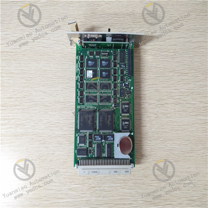
Part Number: IS200BICLH1BBA
Manufacturer: GE Vernova
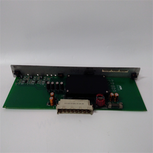
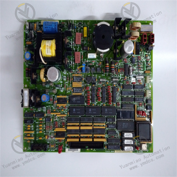
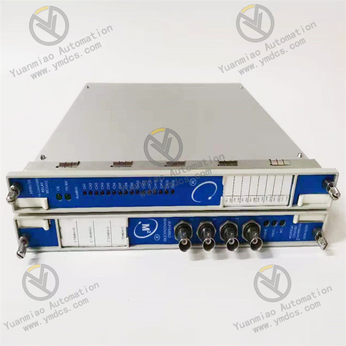
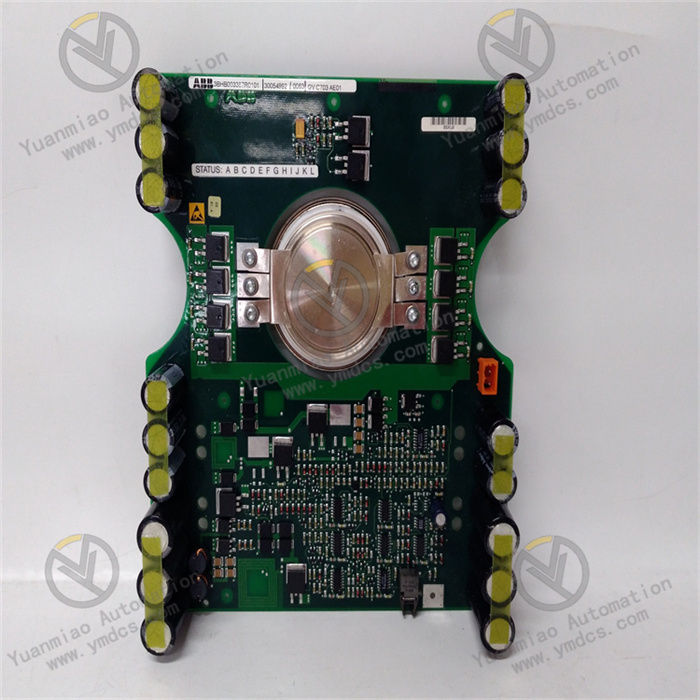
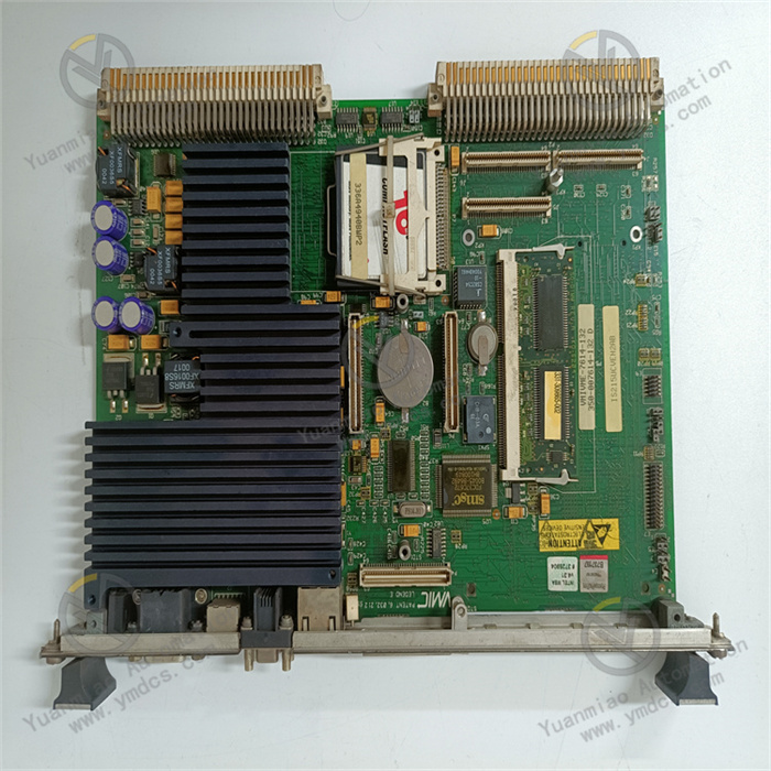
Compatible System: Exclusively designed for GE Speedtronic Mark VI simplex / triple redundant VME rack turbine control system, mandatorily installed only in Rack Slot 5 with no cross-slot mounting. It serves as the signal relay hub between Innovation Series drive main control unit and BPIA/BPIB bridge personality interface boards & SCNV signal conversion boards, undertaking drive command forwarding, temperature monitoring, fan speed regulation, contactor status detection and fault message upload, acting as a core link board for closed-loop control of unit excitation IGBT power modules.Product Definition: BICL series IGBT drive source bridge PCB interface board equipped with a 1024-bit serial ID memory chip for permanent board identity storage. It integrates 4 relays, 3 bridge rectifiers and multiple logic ICs. Dual P1/P2 128-pin VME backplane connectors connect to system bus to realize drive command transmission, 4-channel RTD temperature sampling, PWM fan speed control, MA/MB contact auxiliary contact detection and centralized fault report. No external front wiring terminals or status LEDs are equipped; all data interaction and self-diagnosis are completed solely via backplane bus.
2. Hardware Structure & Six Functional Units
2.1 Dual VME Backplane Bus Interaction Unit
2.2 IGBT Drive Command Bridging & Relay Unit
2.3 Multi-Channel Status & Analog Acquisition Unit
2.4 PWM Fan Speed Regulation & Relay Output Unit
2.5 Hardware ID Storage & Power-On Self-Test Unit
2.6 Slot Position Limitation & Industrial Conformal Coating Unit
3. Detailed Technical Specifications
(1) Core Hardware & Interface Parameters
| Item | Specification |
|---|---|
| Model | IS200BICLH1BBA Mark VI BICL Bridge Interface Board |
| Platform | GE Speedtronic Mark VI VME Rack Gas & Steam Turbine Control System |
| Mandatory Mounting Slot | Fixed Slot 5 only; cross-slot installation prohibited |
| Backplane Interfaces | Dual P1/P2 128-pin gold-plated VME connectors; no external front terminals |
| Onboard Components | 4 signal relays, 3 bridge rectifiers, 1024-bit serial ID chip, EPLD logic array |
| Acquisition Channels | 4×RTD temperature inputs; 2×MA/MB contact detection inputs (24~115V AC/DC) |
| Output Functions | PWM fan speed control signal; interlock relay dry contact output |
| Onboard Auxiliary Parts | No fuses, test points, LED indicators or adjustable hardware |
| Identification Mode | Automatic board ID reading and configuration comparison during power-on |
(2) Electrical & Communication Parameters
- Power Supply: Multi-channel standard DC power fed from Mark VI VME rack backplane
- Contact Sensing Range: 24V~115V AC/DC universal, sampling current 4~10mA
- Bus Protocol: Native Mark VI VME parallel backplane bus with no extra protocol converter
- Fault Upload Mode: Fault data is transmitted as character strings to CPU and SCADA HMI via backplane bus
- Hot Swap Regulation: Hot plugging while rack is energized is strictly forbidden, which causes backplane short-circuit and permanent burnout of logic & memory chips.
(3) Environmental Operating Parameters
- Operating Temperature: -20℃ ~ +65℃
- Storage & Transport Temperature: -40℃ ~ +70℃
- Humidity: 5%~95%RH non-condensing, no corrosive gas or salt fog deposition
- Ingress Rating: IP20 for installation inside sealed industrial control cabinets only
(4) Mechanical Mounting Dimensions
- Mounting Method: Horizontal plug-in into single VME rack slot, secured with two front panel locking screws
- Net Weight: Approx. 0.75kg
- PCB Finish: Anti-oxidation gold plating on traces and backplane contacts for repeated maintenance plugging
- Structure: Integrated single-piece VME standard width board with no detachable subassemblies
4. Product Advantages
- Hierarchical isolation of drive loops prevents EMI interference from high-power IGBT circuits from infiltrating the main control CPU, eliminating system spurious trips and master board hardware damage at the hardware level.
- All-in-one monitoring of temperature, contactor status, fan operation and subordinate board faults enables direct fault location via upper diagnostic software without on-site wiring disassembly, drastically shortening unit outage troubleshooting duration.
- Physical and printed dual slot restriction eliminates configuration mismatch errors caused by human misinstallation, avoiding drive command loss and power device runaway safety hazards.
- Factory preprogrammed board ID eliminates on-site configuration modification during spare part replacement; the system automatically matches project parameters after power-on with no program download or address reconfiguration required.
- Wear-free component-free design requires only annual screw tightening inspection during unit overhaul cycles with minimal routine maintenance workload.
- Native triple redundant architecture support enables fault tolerance for large generating units; two redundant boards can take over control logic if one unit fails to prevent immediate unit shutdown.
5. Application Scenarios
Combined-Cycle Thermal Power Gas Turbine Main Control System
Petrochemical Large Process Compressor Control System
Deployed in Mark VI control systems of cracking gas compressors and process drive turbines for command forwarding of high-power IGBT variable-frequency modules, overheat protection and contactor loop monitoring to guarantee stable signal transmission for continuous chemical production and prevent process interruption from interlock misoperation.
Legacy Mark VI System Retrofit & Spare Part Replacement
Preventive Spare Part Inventory for Power Plants