Description
1. Overview
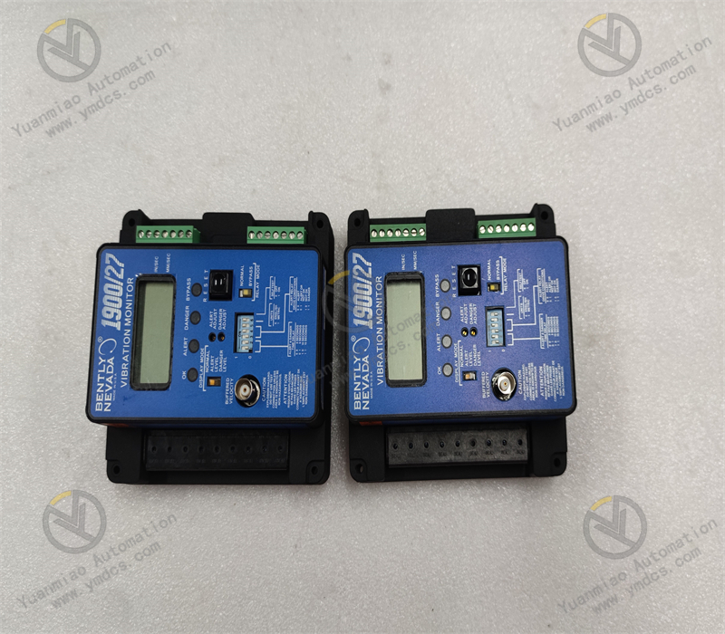
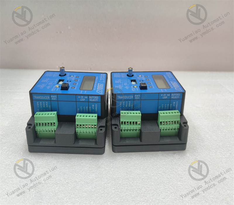
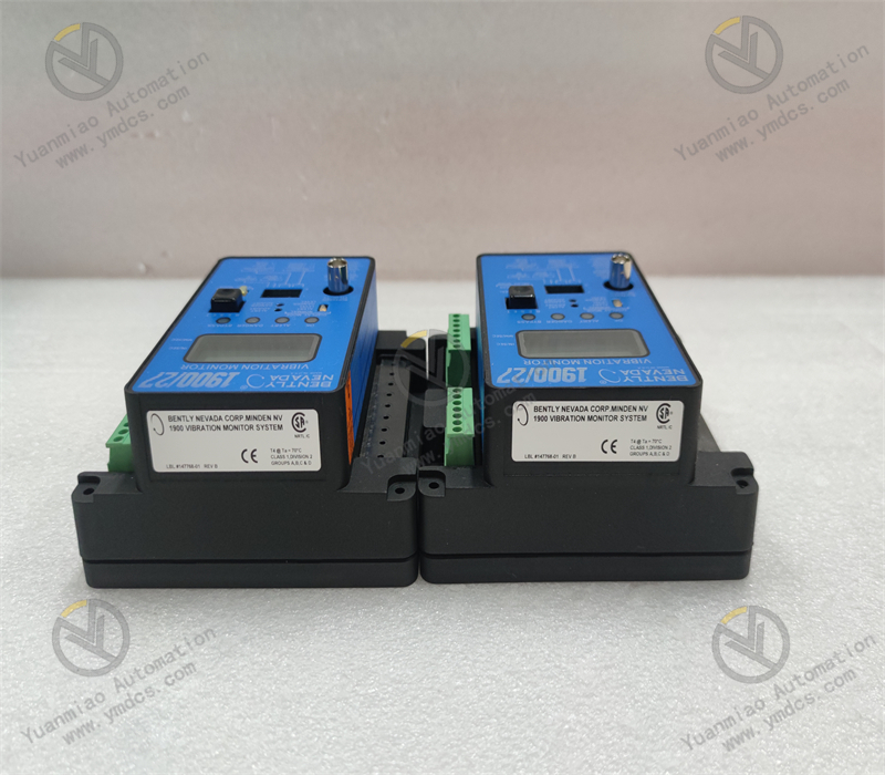
Bently Nevada 1900/27 is a single‑channel standalone case‑vibration monitoring module of Baker Hughes Bently Nevada 1900 series local intelligent monitoring devices, designed for online monitoring of housing vibration and structural vibration of industrial rotating machinery. Different from rack‑based centralized monitoring systems, this unit adopts a local wall‑mount / small‑cabinet standalone structure. It does not rely on 3500 or 1701‑series racks and can independently complete vibration signal acquisition, calculation, alarm output and signal transmission. It serves as a lightweight core device for condition monitoring of medium‑and‑small‑sized units, auxiliary equipment and distributed assets.
The 1900/27 vibration monitoring module is specially compatible with Velomitor velocity transducers and piezoelectric accelerometers for case‑vibration measurement to accurately acquire absolute‑vibration parameters of equipment housings. Equipped with a 24‑bit high‑precision signal‑processing chip, it features low‑noise wide‑band measurement, programmable parameter configuration, standard analog transmission output and relay alarm output. It delivers high measurement accuracy, solid operational stability and excellent environmental adaptability. Widely deployed for rotating auxiliary machinery such as fans, pumps, small compressors, gearboxes and motors in thermal‑power, chemical, oil‑gas, metallurgical and water‑treatment industries, it provides over‑vibration early warning, fault prediction and equipment protection. It is a standardized preferred solution for plant condition‑based maintenance, legacy measuring‑point retrofits and monitoring‑system capacity expansion for distributed equipment.
2. Functions and Features
2.1 Core Functions
High‑precision Case‑vibration Monitoring: Single‑channel independent vibration acquisition supporting acceleration and velocity measurement. It accurately captures high‑frequency and low‑frequency housing‑vibration variations and tracks real‑time vibration amplitude, covering full‑operating‑condition monitoring requirements for general industrial auxiliary machinery.
User‑programmable Custom Configuration: On‑site adjustment of measurement range, frequency pass‑band, alert threshold, danger threshold and delay parameters. Custom monitoring parameters can be matched according to process characteristics of fans, pumps, motors and other machinery to comply with multi‑scenario monitoring standards.
Standard 4‑20 mA Analog Transmission Output: Linearly converts vibration readings into industry‑standard 4‑20 mA signals for direct connection to DCS, PLC and host monitoring systems, enabling remote data upload, trend logging and centralized supervision.
Multi‑level Alarm and Protection Output: Configurable Alert / Danger two‑level alarm logic with passive relay‑contact outputs. It supports local alarm indication and remote alarm reporting and can interlock with equipment protection to mitigate faults caused by excessive vibration.
Comprehensive Signal Self‑check and Fault Diagnosis: Built‑in detection for sensor open‑circuit, short‑circuit, signal anomaly and module hardware faults. It actively identifies measuring‑point failures and reports fault codes to avoid invalid readings, missed alarms and false trips, ensuring monitoring reliability.
Rack‑free Standalone Operation: Operates with independent power supply, acquisition and output without dedicated monitoring racks. Flexible installation and simplified cabling make it ideal for auxiliary‑equipment monitoring with distributed layouts and no centralized monitoring cabinets.
Wide‑band Low‑noise Signal Processing: 24‑bit high‑resolution signal acquisition with ultra‑low internal noise. It detects minor vibration anomalies and gives advance warning of latent defects including bearing wear, rotor unbalance, base looseness and mechanical resonance.
2.2 Product Characteristics
Superior Measurement Accuracy: 24‑bit high‑precision AD sampling delivers wide dynamic range and high resolution with mature signal‑processing algorithms. It captures subtle vibration changes to meet precision condition‑monitoring and fault‑diagnosis requirements for industrial machinery.
Broad Industrial Environmental Compatibility: Industrial‑grade wide‑temperature construction tolerates temperature cycling, dust and moderate humidity. It permits long‑term local field installation without temperature‑controlled cabinet protection and outperforms conventional instruments in harsh environments.
Robust Anti‑interference Performance: Multi‑stage EMC electromagnetic‑compatibility defenses suppress electromagnetic disturbance from variable‑frequency drives, high‑voltage apparatus and power cables. It prevents data jitter, value drift and false alarms for high‑interference industrial sites.
Lightweight Integrated Stand‑alone Design: Compact all‑in‑one unit integrating power supply, acquisition, computation, alarming, transmission and communication. No external signal‑conditioning modules are required, offering easy installation, simple commissioning and low maintenance costs.
Reliable Long‑term Continuous Operation: Selected industrial‑grade components yield low power consumption and low heat generation with negligible parameter drift. It supports 7×24‑hour non‑stop service with stable long‑term performance and minimal need for recalibration.
User‑friendly Operation‑and‑maintenance with High Fault Tolerance: Supports local keypad configuration and host‑based communication setup for flexible parameter modification. Intuitive fault codes enable fast localization of measuring‑point anomalies, improving troubleshooting efficiency for large‑scale auxiliary‑equipment standardization and retrofits.
3. Specifications
| Item | Specifications |
|---|---|
| Model | 1900/27 |
| Device Type | Single‑channel Stand‑alone Case‑vibration Monitoring Module |
| Brand & Manufacturer | Bently Nevada (Baker Hughes) |
| Compatible Sensors | Velomitor Velocity Transducers, Piezoelectric Accelerometers |
| Measurement Channel | Single‑channel vibration acquisition |
| Frequency Range | 2 Hz ~ 20 kHz |
| Maximum Measured Acceleration | 20 g (peak) |
| Input Sensitivity | 100 mV/g |
| Maximum Differential Input Voltage | 4 V (peak‑to‑peak) |
| Sampling Resolution | 24‑bit high‑precision AD sampling |
| Power Supply | 24 VDC industrial regulated power |
| Power Consumption | 7.7 W |
| Analog Output | Standard 4‑20 mA linear transmission output |
| Alarm Output | Two‑level programmable passive relay‑contact outputs (Alert / Danger) |
| Communication Interface | RS232, RS485 for configuration |
| Operating Temperature | ‑40 ℃ ~ +85 ℃ |
| Storage Temperature | ‑45 ℃ ~ +90 ℃ |
| Ambient Humidity | 5%‑95% RH, non‑condensing |
| Ingress Protection | Industrial field‑grade for local on‑site installation |
| Operational Features | Low noise, high accuracy, low temperature drift, fault self‑diagnosis, user‑programmable parameters |
4. Operating Principle
The Bently Nevada 1900/27 vibration‑monitoring module works on the principle of high‑precision dynamic vibration‑signal acquisition and digital processing. Connected to external case‑vibration sensors, it acquires acceleration and velocity physical quantities from rotating‑machine housings and completes signal conditioning, sampling‑computation, logic judgment and signal transmission.
During equipment operation, vibration sensors convert mechanical housing vibration (displacement, velocity, acceleration) into weak analog electrical signals fed into the 1900/27. Internal front‑end conditioning circuits filter noise, suppress interference and shape raw input to reject field clutter and invalid high‑frequency noise. A 24‑bit high‑precision AD converter digitizes the conditioned signal. Embedded algorithms calculate RMS, peak and frequency‑domain values to interpret real‑time equipment‑vibration status.
Computed vibration values are continuously compared against user‑defined Alert and Danger thresholds. When readings exceed the Alert threshold, level‑one alarm is triggered; crossing the Danger threshold activates level‑two alarm and relay‑contact outputs for local annunciation and remote interlock protection. Meanwhile, vibration values are linearly converted to 4‑20 mA analog signals and transmitted to DCS / PLC host systems for trend logging, remote monitoring and condition analysis.
In addition, the module continuously monitors sensor‑loop continuity, signal amplitude and hardware health. Sensor open‑circuit, short‑circuit, signal abnormality or module hardware faults are actively detected and flagged with fault codes. This prevents invalid measurement data and guarantees authenticity, accuracy and continuity of equipment condition monitoring.
5. Application Scenarios
Vibration Monitoring for Industrial Auxiliary Machinery: Widely used for ID fans, forced‑draft fans, circulating‑water pumps, booster pumps, small compressors, gearboxes and large motors in thermal‑power, chemical, oil‑gas, metallurgical and water‑treatment plants. It realizes online housing‑vibration monitoring and over‑limit protection for assets without centralized rack‑based monitoring systems.
Local Monitoring of Distributed Equipment: Suited for sites with geographically dispersed machinery and no centralized monitoring cabinets where rack‑system deployment is impractical. Its rack‑free standalone architecture delivers accurate per‑asset monitoring for retrofits and new measuring‑point additions.
Legacy Simple Measuring‑point Upgrade: Replaces outdated vibration transmitters, basic vibration meters and non‑alarmed monitoring devices. It improves measurement accuracy, fault‑diagnosis capability and interlock‑protection reliability for plant intelligent and standard‑technical‑transformation projects.
Fault Prediction and Condition‑based Maintenance: Long‑term vibration‑trend recording and precise measurement enable early detection of rotor unbalance, bearing wear, base loosening, piping resonance and equipment eccentricity. It supplies data support for scheduled maintenance, condition‑based service and fault forecasting.
Light‑weight Monitoring for Medium‑and‑small‑sized Units: Meets lightweight monitoring requirements for medium‑and‑small‑sized complete sets, mobile machinery and process packages. Large‑scale monitoring infrastructure is unnecessary; cost‑effective vibration safety supervision and remote data transmission are achieved.
Deployment in Harsh Industrial Sites: Wide‑temperature operation together with dust‑ and electromagnetic‑interference resistance permits direct local installation at equipment skids, shop floors and sheltered outdoor locations for high‑temperature, dusty and electrically noisy industrial environments.
6. Common Faults and Troubleshooting
6.1 Fixed, unchanging or frozen measurement readings
Root Causes: Degraded or defective sensor; broken / loose sensor cable; faulty module acquisition channel; mismatched measuring‑range setting or excessive filtering suppressing valid vibration signals.
Solutions: Inspect sensor physical condition and mounting tightness to rule out damage and looseness. Check cable continuity and connector integrity and retighten connections. Verify module range, frequency pass‑band and filter parameters and restore standard configuration. If readings remain static with all external items verified normal, the module acquisition channel is defective; replace the 1900/27 module.
6.2 Frequent data jitter, abnormal fluctuation and irregular drift
Root Causes: Severe on‑site electromagnetic interference; unshielded sensor cable or poor shield‑grounding; loose sensor mounting introducing parasitic resonance; inappropriate filter settings; unstable supply voltage with excessive power‑supply ripple.
Solutions: Implement single‑end shield grounding for signal cables and route them away from power and variable‑frequency drive cables. Retighten sensor mounting to eliminate extra induced vibration. Optimize filter and sampling parameters. Measure power‑supply stability and replace regulated power supply if needed. If fluctuation persists after field rectification, suspect degraded module signal‑processing hardware and replace the module.
6.3 Frequent / false alarms without actual excessive vibration
Root Causes: Improper alarm thresholds and delay settings; interference noise captured by acquisition chain; sensor zero‑point drift; corrupted module parameters or firmware anomaly.
Solutions: Re‑calibrate Alert / Danger thresholds and alarm delays to match equipment process criteria. Improve cabling and grounding to mitigate electromagnetic interference. Perform sensor zero‑point calibration. Restore factory defaults and re‑configure parameters. Replace module if false alarms recur.
6.4 Abnormal 4‑20 mA transmission; no DCS reading or large reading deviation
Root Causes: Incorrect or open analog‑output wiring; transmission‑range mismatch with host system; defective module transmission‑output circuit; out‑of‑specification loop load resistance.
Solutions: Check 4‑20 mA output polarity and circuit continuity for wiring faults. Align module transmission‑range settings with DCS range parameters. Measure actual loop current and compare against expected values. Re‑configure if parameter mismatch exists; replace module for hardware output failure.
6.5 Module reports channel fault / sensor‑error code
Root Causes: Damaged sensor with lost sensitivity; short‑circuit, open‑circuit or water ingress in signal cable; oxidized connectors with degraded insulation; damaged module input channel.
Solutions: Power off and test sensor and cable insulation and continuity. Clean oxidized connectors and apply moisture‑proof treatment. Replace defective sensor or cable. If fault persists after eliminating field‑side anomalies, the module input channel is damaged; install a new 1900/27 module.
6.6 Module fails to power‑on; no display, no operational status
Root Causes: Abnormal external supply voltage, reversed polarity; tripped circuit‑breaker or broken power wiring; damaged on‑board power‑supply circuit, hardware burnout.
Solutions: Measure input supply voltage and verify polarity. Troubleshoot upstream power loop and restore correct power. If power conditions are normal yet the unit remains inoperative, module hardware failure is confirmed; replace with spare unit.