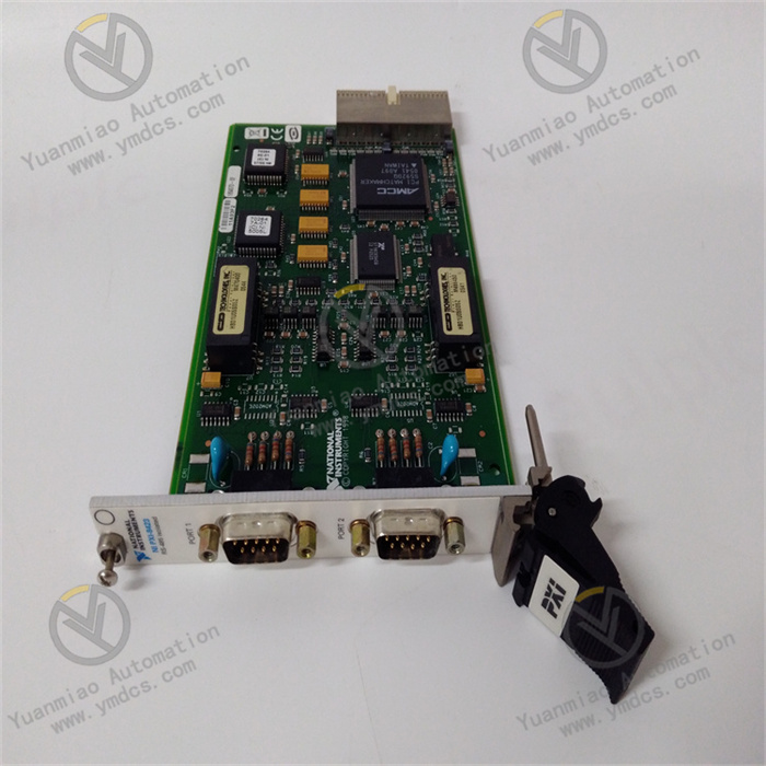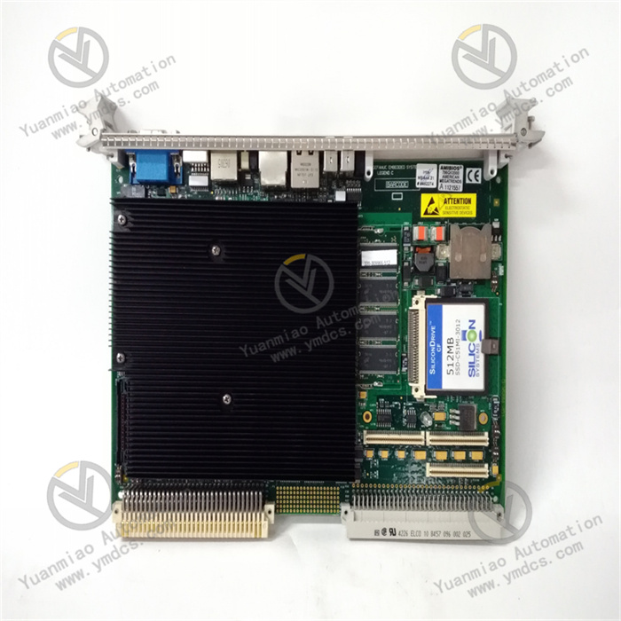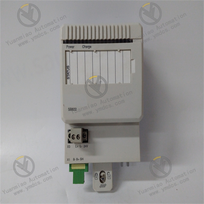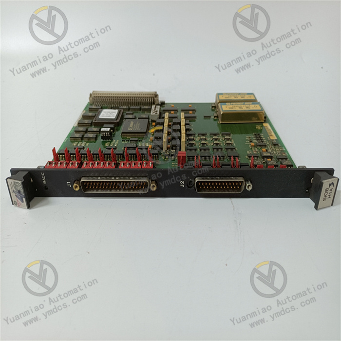
Description
1. Overview
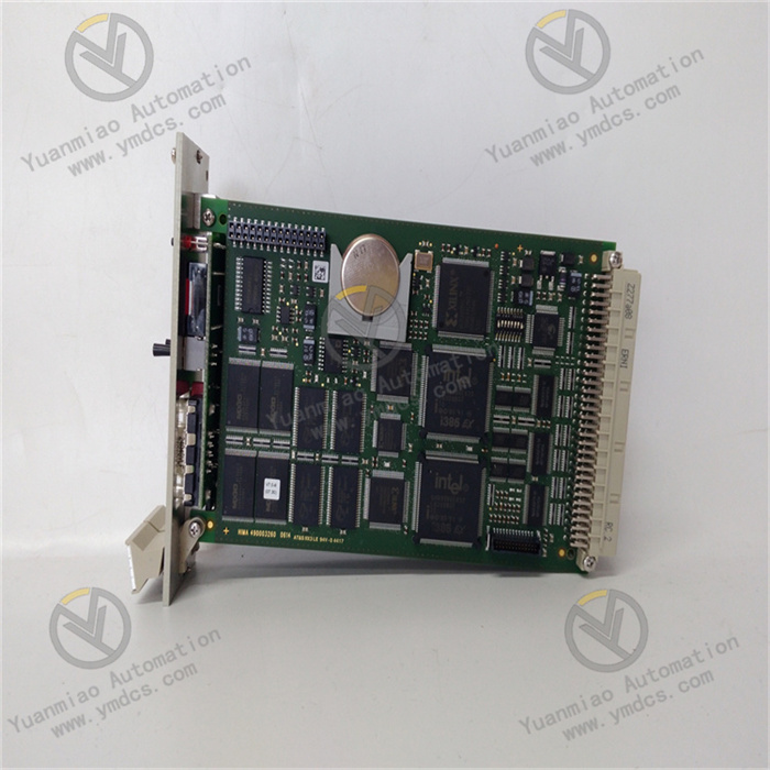
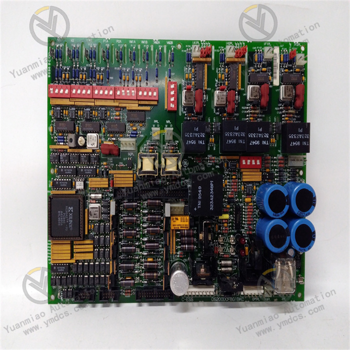
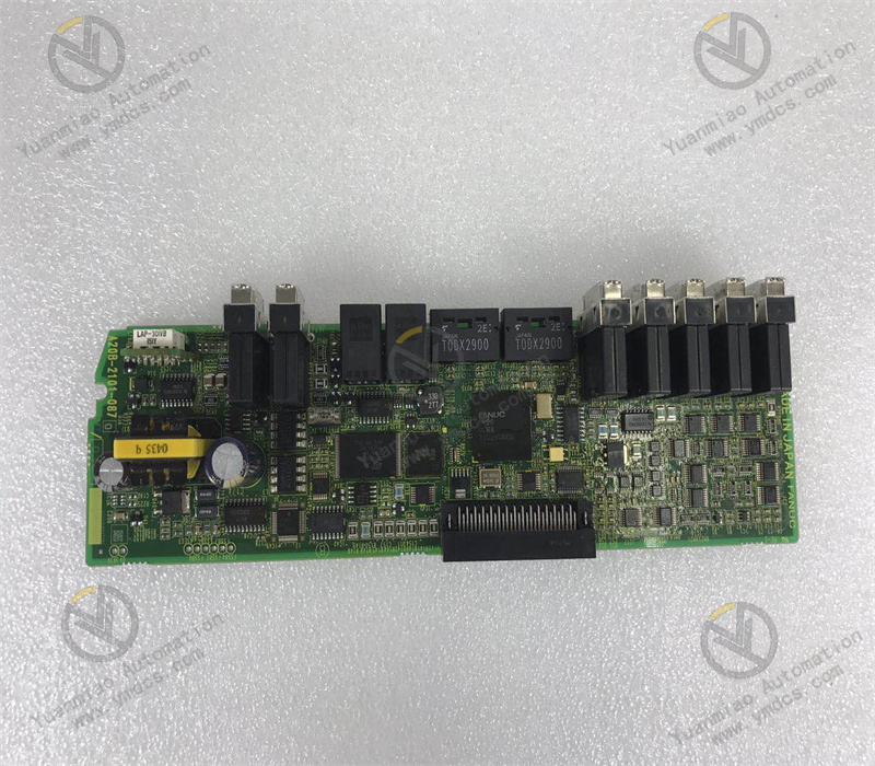
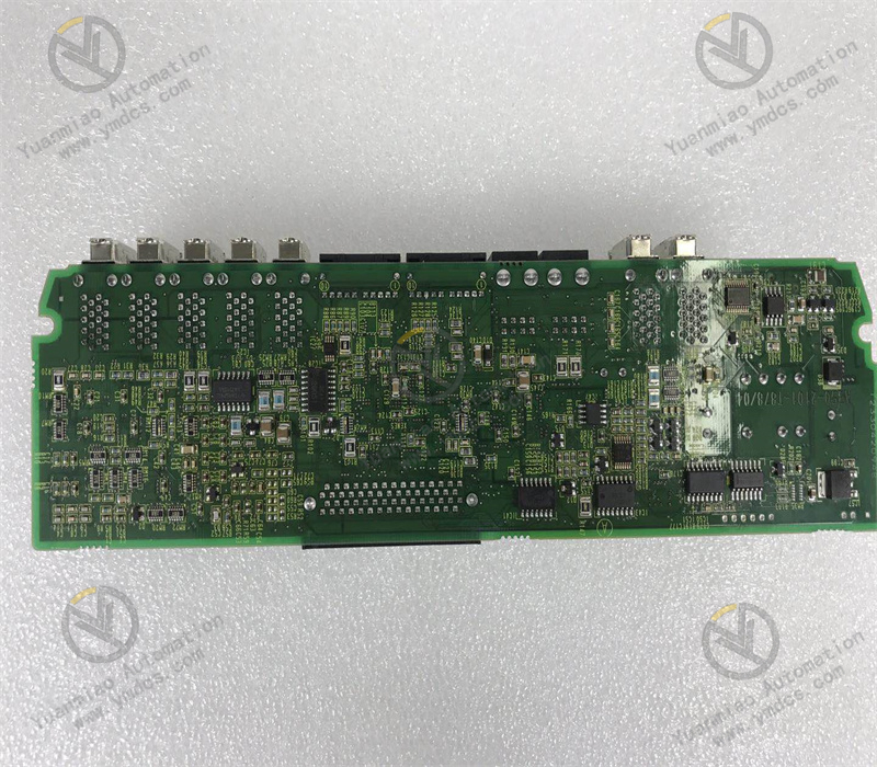
GE Fanuc A20B‑2101‑0870 is a dedicated servo‑spindle control board for FANUC / GE Fanuc CNC systems. As a core circuit board of the servo drive system for CNC machine tools, it is widely compatible with classic CNC system models such as 0i, 16i and 18i. This board undertakes key functions including servo‑axis signal calculation, spindle drive control, position‑feedback acquisition, servo‑link communication, fault detection and protection. It serves as the critical hardware carrier for 3‑axis / 4‑axis interpolation, spindle speed regulation, positioning machining and closed‑loop servo control of CNC machine tools.
Adopting industrial‑grade high‑precision circuit design, the A20B‑2101‑0870 integrates units for servo signal processing, drive logic computation, encoder signal decoding and hardware overload protection. It features high calculation accuracy, fast response, strong anti‑interference performance and reliable operation, and is suitable for harsh working conditions such as high‑speed cutting, precision positioning and continuous machining. As a frequently‑used maintenance‑replacement spare part for CNC machine tools, this board offers excellent compatibility. It can directly replace old faulty boards of the same series without modifying system parameters or machine programs. After power‑on commissioning, normal production capacity of the machine tool can be quickly restored. It is applicable to system maintenance and hardware upgrade of various vertical / horizontal machining centers, CNC lathes and milling machines.
2. Functions and Features
2.1 Core Functions
Closed‑loop Calculation and Control of Servo Axes: Performs interpolation calculation as well as position‑loop, speed‑loop and current‑loop closed‑loop control for each servo axis of the CNC system. It accurately executes movement, positioning and interpolation commands issued by the system, ensuring smooth feed and precise positioning of machine‑tool axes to meet requirements for precision machining.
Spindle Drive and Speed Regulation Control: Matches the machine‑tool spindle servo unit, outputs spindle speed‑regulation and start‑stop logic signals, and adjusts spindle speed and torque output in real time. It supports constant‑speed and constant‑torque machining modes, and adapts to various spindle‑based machining processes including milling and turning.
Encoder Signal Acquisition and Decoding: Collects feedback signals from servo‑motor and spindle encoders in real time, and rapidly parses position, speed and angle data. It continuously compares command values against actual operating values and dynamically corrects running deviations to avoid positioning drift and dimensional errors of machined workpieces.
Servo‑System Communication Interaction: Establishes a data communication link between the CNC main‑control system and servo amplifiers / spindle drives. It transmits control commands, operating status and feedback data in both directions to guarantee command synchronization and real‑time data exchange of the servo system, realizing overall‑machine coordinated control.
Comprehensive Hardware Self‑diagnosis and Protection: Monitors abnormal operating conditions including servo overload, over‑current, over‑voltage, under‑voltage, encoder faults, communication timeout and drive‑circuit failures. It triggers servo alarms and axis‑lock protection accurately and reports fault codes to the system, preventing secondary damage to motors, drives and the board itself.
Dynamic Machining‑error Compensation: Supports calculation for machine‑tool pitch compensation, backlash compensation and positioning‑error compensation. It corrects mechanical errors of the machine tool via precise logical computation, improving workpiece consistency and finished‑part accuracy for high‑precision CNC machining scenarios.
System‑parameter Storage and Adaptation: Equipped with a dedicated storage unit to store servo‑axis parameters, spindle parameters and machine‑tool adaptation parameters. It is fully compatible with parameter logic of matching CNC systems, ensuring stable retention and invocation of machine‑tool parameters and avoiding equipment abnormalities caused by parameter loss.
2.2 Product Features
High‑precision and High‑speed Computing Performance: Built with dedicated servo computing chips for low‑calculation latency and fast response. It accommodates high‑speed feed, rapid positioning and precision‑cutting conditions of machine tools, effectively eliminating machining jitter, edge defects and positioning overshoot.
Machine‑tool‑grade Anti‑interference Design: Optimized for electromagnetic interference from inverters, servo motors and high‑frequency equipment in machine‑shop environments. Multi‑stage filtering, signal shielding and circuit anti‑interference mechanisms are implemented to withstand complex electromagnetic conditions without signal disorder or false logic triggering during long‑term operation.
Full‑series High Compatibility: Fully compatible with mainstream GE Fanuc and FANUC 0i / 16i / 18i CNC systems. Pin definitions, communication protocols and hardware specifications comply with original‑manufacturer standards. Replacement of legacy boards requires no rewiring or parameter reconstruction.
Long‑term Industrial‑grade Durability: Manufactured with high‑temperature‑resistant, anti‑aging PCB substrates and rugged components. It withstands high cabinet temperature, dust, minor vibration and temperature cycling, delivering extremely low failure rates under 24‑hour continuous mass‑production operation.
Fast Commissioning without Complex Debugging: Pre‑loaded with standardized factory firmware and factory‑calibrated functions. After replacing a faulty board, only simple servo‑parameter verification and home‑position calibration are required to resume normal machining, greatly reducing maintenance downtime.
3. Specifications
| Parameter Item | Technical Specification |
|---|---|
| Model | A20B‑2101‑0870 |
| Device Type | CNC servo‑spindle control board |
| Compatible Systems | GE Fanuc / FANUC 0i, 16i, 18i series CNC systems |
| Core Functions | Servo‑axis closed‑loop control, spindle speed‑regulation drive, encoder‑signal decoding, servo communication, fault self‑diagnosis & protection, machining‑error compensation |
| Power Supply | Standard CNC system DC24V, DC5V power supply |
| Controllable Axes | Supports multi‑axis servo interpolation (compatible with mainstream 3‑axis / 4‑axis machine tools) |
| Signal Processing | High‑speed digital closed‑loop calculation, differential encoder‑signal decoding |
| Protection Features | Over‑voltage, under‑voltage, over‑current, overload, communication‑fault and encoder‑fault interlock protection |
| Operating Temperature | 0 ℃ ~ +65 ℃ (standard machine‑tool cabinet condition) |
| Ambient Humidity | 5%‑95% RH, non‑condensing |
| Ingress Protection | IP20 (for cabinet‑internal installation) |
| Mounting Method | Slot‑mounted embedded installation on CNC main‑board |
| Application Equipment | CNC lathes, machining centers, milling machines, precision CNC processing equipment |
4. Working Principle
The GE Fanuc A20B‑2101‑0870 servo control board implements a full‑closed‑loop servo‑control workflow: System Command Reception → Closed‑loop Calculation → Drive‑signal Output → Feedback‑signal Acquisition → Fault Self‑diagnosis & Correction. Upon machine‑tool power‑on, the board completes hardware self‑test, parameter initialization and bus‑protocol matching before entering normal servo‑control operation.
Axis‑movement, spindle‑rotation and machining‑interpolation commands issued by the CNC main controller are transmitted to this board. Combined with preset machine‑tool parameters, the core computing unit performs precise position‑loop, speed‑loop and current‑loop calculations. Standardized servo drive signals are generated and sent to servo amplifiers and spindle drives to control accurate rotation, feed and positioning of servo motors. Meanwhile, the board continuously collects differential feedback signals from servo‑motor and spindle encoders. It compares commanded values against actual operating values in real time, dynamically compensates deviations and corrects positioning errors and speed fluctuations to guarantee machining accuracy and stability.
Throughout operation, the on‑board monitoring unit continuously tracks supply voltage, output current, communication status, encoder signals and load conditions. Once overload, short‑circuit, signal abnormality, communication timeout or parameter corruption is detected, hardware interlock protection is activated immediately. Drive outputs for faulty axes are cut off, machine‑tool operation is locked, and alarm codes are reported to the CNC system to prevent fault escalation. Servo parameters are persistently stored to avoid parameter loss after restart and ensure continuous and stable precision machining.
5. Application Scenarios
Precision CNC Machining Centers: Used for servo‑axis interpolation control, precise spindle speed regulation and positioning‑error compensation in vertical and horizontal machining centers. It ensures high‑accuracy milling, drilling and boring for molds, precision components and hardware workpieces, stabilizing overall machining quality.
Control Systems for CNC Lathes: Applied to servo feed and spindle control of various CNC lathes. It realizes high‑speed feed, precise positioning and constant‑speed turning, eliminating workpiece dimensional deviation and excessive surface roughness and guaranteeing consistency in mass turning production.
CNC Milling Machines & Special‑purpose Machine Tools: Deployed in CNC milling machines, drill‑tap centers and automated special‑purpose processing equipment. It executes multi‑axis interpolation logic and servo‑drive control for high‑frequency, heavy‑duty continuous‑machining conditions.
Maintenance Replacement for GE / FANUC CNC Systems: Serves as a universal replacement board for 0i / 16i / 18i systems. It directly replaces aged, error‑prone or computation‑defective legacy servo boards to resolve servo alarms, axis standstill, positioning deviation and spindle malfunctions.
Retrofit of Legacy CNC Equipment: For older machine tools suffering from degraded accuracy, unstable servo performance and frequent alarms, board replacement optimizes servo performance, improves machining precision and operational reliability, and achieves cost‑effective intelligent equipment upgrade.
6. Common Faults and Troubleshooting
6.1 Servo alarm triggered, machine‑tool axes cannot move
Fault Causes: Defective servo‑calculation circuitry on board, abnormal communication link, unstable board power supply, damaged encoder‑signal decoding unit, corrupted parameter storage.
Solutions: Check CNC servo alarm codes; verify 24 V and 5 V supply voltages to eliminate power fluctuation and poor‑connection faults. Clean board gold‑fingers and system slots, then re‑seat and fasten the board. Reload machine‑tool servo parameters and reboot to re‑initialize servo logic. If alarms persist after confirming servo‑motor, drive and encoder are intact, the board hardware is defective; replace A20B‑2101‑0870.
6.2 Excessive positioning deviation, unstable machining dimensions, out‑of‑tolerance workpiece accuracy
Fault Causes: Degraded closed‑loop calculation accuracy of the board, failed error‑compensation unit, signal‑decoding drift, calculation deviation caused by long‑term high‑temperature ageing.
Solutions: Re‑calibrate pitch‑compensation and backlash‑compensation parameters. Inspect encoder signal cables for interference and loose connections. Improve cabinet heat dissipation to reduce board operating temperature. Replace the board if accuracy deviations cannot be eliminated.
6.3 Unstable spindle speed, abnormal speed regulation, spindle alarms
Fault Causes: Malfunction of on‑board spindle‑control logic unit, abnormal spindle‑signal output, damaged speed‑regulation calculation circuit, lost spindle‑communication packets.
Solutions: Inspect spindle drive and spindle motor to rule out peripheral faults. Check spindle‑control signal wiring and repair cable damage or interference. Re‑match spindle speed‑regulation parameters. Replace the board if spindle malfunctions remain unresolved.
6.4 Black screen on power‑on, failure to enter machining interface, boot‑up alarms
Fault Causes: Damaged core calculation chip, lost program / parameters, failed communication between board and main‑board, hardware self‑test failure.
Solutions: Power‑cycle the machine and re‑seat the board to fix contact issues. Back‑up and re‑import basic system parameters to resolve parameter loss. Replace the servo board if boot‑up failure persists with confirmed intact main‑board and power‑supply modules.
6.5 Intermittent servo alarms, mid‑cycle machine stops, occasional axis dropout
Fault Causes: Component ageing, performance degradation under high temperature, cold‑solder joints, reduced anti‑interference capability, unstable communication links.
Solutions: Optimize cabinet earthing and shielding to mitigate shop‑floor electromagnetic interference. Enhance ventilation and heat dissipation to avoid board overheating. Fasten board connectors and slots to eliminate contact risks. Replace with a new board if intermittent faults occur frequently.