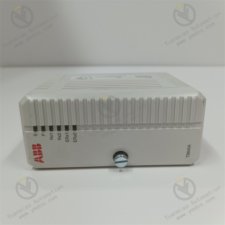
Description
Functional Purpose:
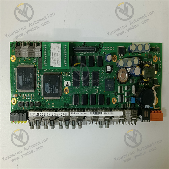
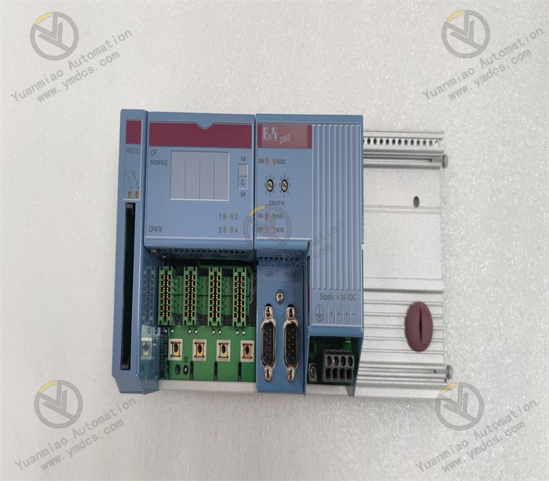
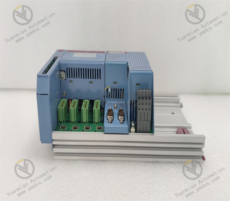
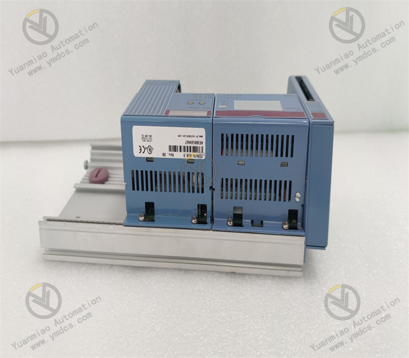
This is a PROFIBUS DP master communication module with an IP67 protection rating, designed to connect B&R PLCs to PROFIBUS DP networks and enable communication between the PLC and other PROFIBUS DP devices.
Transmission Rate:
Supports a maximum transmission rate of 12 Mbit/s, enabling fast and efficient data transfer to meet the high real-time communication requirements of industrial sites.
Connectivity:
Can connect up to 31 PROFIBUS DP devices, offering strong networking capabilities to satisfy the multi-device connection needs of most industrial automation systems.
Interface Type:
Features a D-Sub 9-pin interface, which provides good stability and compatibility for easy connection to other devices.
Power Requirements:
Operates at a power voltage of 24VDC with a power consumption of 5W, making it easy to obtain stable power supply in industrial environments due to its conventional power requirements.
Operating Temperature:
Functions within a temperature range of -20°C to 60°C, demonstrating high environmental adaptability and stability across a wide range of industrial temperature conditions.
Enclosure Protection Rating:
With an IP67 protection rating, it is dustproof and waterproof, suitable for harsh industrial production environments such as humid and dusty sites.
How to Install and Configure the B&R 7CP476-010.9 Module?
I. Pre-Installation Preparation
- Confirm Module Functionality and System Compatibility
- Refer to the product manual to clarify the module's purpose (e.g., whether it is a PLC controller, communication module, I/O module, etc.), supported bus protocols (e.g., Ethernet/IP, PROFINET, CANopen, etc.), and compatible hardware platforms (e.g., B&R's ACOPOS series, X20 system, etc.).
- Ensure the controller firmware version is compatible with the module (you may need to upgrade the main controller firmware in advance).
- Prepare Tools and Environment
- Tools: Screwdriver, anti-static wristband, suitable cables (e.g., Ethernet cables, power cables).
- Environment: Operate with power off, ensure the installation location is well-ventilated, free from strong electromagnetic interference, and meets industrial protection rating requirements (e.g., IP20, etc.).
II. Hardware Installation Steps
- Install the Module in a Control Cabinet or Rack
- Insert the module into the designated slot of the rack (pay attention to matching the slot number with the module type).
- Tighten the locking devices on the module's side to ensure reliable electrical connections.
- Snap the module into a standard rail (e.g., DIN rail), ensuring the slots are aligned.
- Secure the module with screws through the mounting holes on both sides to ensure stability.
- Rail Mounting (Common for Industrial Modules):
- Rack Mounting (e.g., B&R's X20 System):
- Connect Power and Communication Cables
- Use a dedicated cable to connect the module to the main controller or host computer (e.g., connect to the PLC's CPU module via Ethernet).
- For distributed I/O modules, connect to the fieldbus (e.g., plug a PROFINET network cable into a switch).
- Connect the corresponding DC power supply (e.g., 24V DC) according to the module's label, paying attention to positive and negative polarities.
- Ensure the power supply capacity meets the needs of the module and its expansion devices.
- Power Connection:
- Communication Connection:
- Connect Peripheral Devices (if applicable)
- If the module supports I/O signals or sensor interfaces, connect the corresponding cables (e.g., encoders, solenoid valves, sensors, etc.) according to their functions, and ensure proper shielding and grounding to reduce interference.
III. Software Configuration and Parameter Setting
- Install Development Environment and Drivers
- If the module is a third-party device or requires a specific communication protocol, import the corresponding GSD files (for buses like PROFINET) or drivers into the software so that the system can recognize the module.
- If using Automation Studio (B&R's integrated development environment), ensure the software version supports the 7CP476-010.9 module.
- Install B&R Programming Software:
- Import Module GSD Files or Drivers:
- Add the Module to the Project
- Open Automation Studio and create a new project or open an existing one.
- In the hardware configuration interface, drag the "7CP476-010.9" module from the device library to the corresponding slot in the rack. The software will automatically assign default parameters (e.g., device address, communication rate, etc.).
- Configure Module Parameters
- If the module is a motion control module, set axis parameters (e.g., motor type, encoder resolution, control mode, etc.).
- If it is an I/O module, define the type of input/output signals, address mapping, and filtering time, etc.
- Configure the module's IP address, subnet mask, and gateway according to network requirements (e.g., for Ethernet communication).
- For bus modules, set the slave address (e.g., CANopen node ID) to ensure no conflicts with other devices on the network.
- Set Communication Parameters:
- Configure Functional Parameters:
- Download Configuration and Test
- Download the hardware configuration and parameter settings to the main controller (e.g., PLC's CPU), and the module will automatically synchronize the configuration.
- Test Communication Connection: Use the diagnostic functions of the programming software to check the module's status (e.g., "online" or "fault") to confirm successful recognition.
- Functional Test: Write simple programs to drive the module and test whether input/output signals, motion control, or communication functions are normal (e.g., reading sensor data, controlling motor operation, etc.).

IV. Common Issues and Troubleshooting
- Abnormal Module Indicator Lights
- Refer to the "Indicator Light Meaning Table" in the manual to determine the fault type (e.g., power failure, communication interruption, overload, etc.).
- Check power connections and cable tightness, reinsert the module, or restart the system.
- Communication Failure
- Confirm whether the IP address or slave address conflicts, and check network cable connectivity (testable using the ping command).
- Ensure the bus protocol settings are correct (e.g., the PROFINET device name matches the configuration).
- Abnormal Functionality
- Check whether parameter configurations meet actual requirements (e.g., incorrect motor parameters may cause failure to operate).
- Monitor the module's status through the programming software's debugging tools and troubleshoot logical errors step by step.