Description
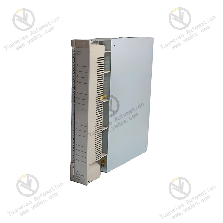
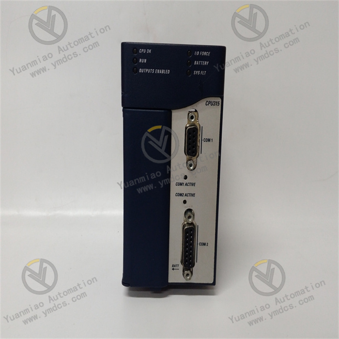
GE IC695CPE310
The GE IC695CPE310 is a processor module for the PACSystems RX7i series of Programmable Automation Controllers (PACs). Serving as the "computational core and control hub" of the PAC system, it integrates the real-time logic control capabilities of a PLC and the complex data processing capabilities of a PC. Its primary responsibilities include executing large-scale user programs, managing distributed I/O networks, processing multi-source data fusion, coordinating cross-system communications, and diagnosing the entire system.\
Its core function is to run multi-language control programs (such as ladder logic and structured text) based on the IEC 61131-3 standard. It collects real-time on-site signals (e.g., industrial sensor data, equipment operating status) from distributed I/O nodes, and after logical operations, process control algorithms (such as multi-loop PID), and data processing, it outputs precise control commands to drive the actions of actuators like valves and motors. Additionally, it features advanced capabilities including high-bandwidth communication, dual-machine hot standby redundancy, massive data storage, and online debugging, making it suitable for the high complexity and high reliability requirements of large and extra-large industrial automation control systems.
With its ultra-high computing performance, strong expandability, excellent redundancy design, and industrial-grade stability, this module is widely used in critical fields such as power grid monitoring, large-scale petrochemical equipment control, rail transit signal control, and integrated metallurgical automation. It is a core pillar component for building large-scale, high-end automation systems.
- Adopts a multi-core 32-bit high-performance RISC processor with a core computing frequency of 1.2GHz, supporting a parallel processing architecture.
- Basic instruction execution speed: 0.02μs per instruction; ladder logic execution speed: 0.05μs per instruction; structured text execution speed: 0.03μs per instruction. It supports a cyclic scan cycle of ≤2ms for 100,000-step programs.
- Supports multi-task priority scheduling, with 16 task priorities configurable (8 of which are real-time tasks). Task switching time is ≤5μs, and interrupt service routine (ISR) response time is ≤1μs, meeting millisecond or even microsecond response scenarios such as power grid fault protection and chemical emergency shutdowns.
- Built-in 32MB non-volatile user program memory (Flash), supporting permanent program storage without the need for a backup battery when power is off.
- 64MB high-speed data memory (RAM), of which 32MB can be configured as a power-off retention area (backed by super capacitor + Flash dual backup, with a backup time of ≥168 hours).
- Supports a maximum external CF card expansion of 256MB for program backup, massive data log storage, firmware updates, and historical data archiving.
- Built-in 1MB high-speed cache (Cache) to improve program execution and data access efficiency.
- Supports expansion via RX7i series distributed racks and remote I/O modules, with up to 16 local expansion racks and 32 remote I/O nodes connectable (supporting Profinet and EtherNet/IP remote I/O).
- Maximum supported I/O points: 32,768 digital points, 4,096 analog points.
- Supports hot-swappable I/O modules and processor modules; replacing modules during system operation does not interrupt the control process.
- Built-in distributed I/O scanner, supporting batch collection and distribution of I/O data with a scanning rate of ≥5,000 points per second. It also supports I/O data filtering and deadband configuration to reduce invalid data transmission.
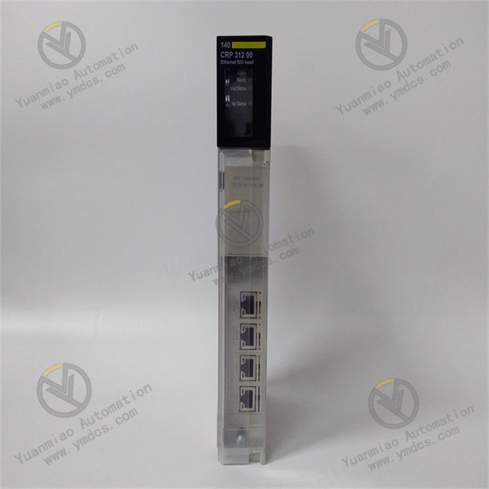
- Integrates 4 Gigabit Ethernet ports (supporting protocols such as Profinet V2.3, EtherNet/IP, Modbus/TCP, and IEC 61850 MMS), 2 RS-485 serial ports (supporting Modbus-RTU and DNP3.0 protocols), and 1 PCIe expansion slot (for expanding interface modules such as fiber optic communication and dedicated industrial buses).
- Supports Ethernet ring network redundancy (Profinet MRP, EtherNet/IP DLR) with a ring network recovery time of ≤20ms.
- Operating temperature: 0℃~60℃; storage temperature: -40℃~85℃.
- Relative humidity: 5%~95% (no condensation).
- Vibration resistance rating: IEC 60068-2-6 (10Hz~500Hz, acceleration 5g).
- Shock resistance rating: IEC 60068-2-27 (peak acceleration 15g, duration 11ms).
- Protection rating: IP20 (rack-mounted), suitable for high-integration installation environments inside control cabinets.
- Dimensions: 140mm×180mm×80mm, installed using the RX7i standard rack.
The 1.2GHz multi-core processor adopts a task-slicing parallel processing architecture, which can assign real-time control logic, data processing, and communication interaction to different cores for independent execution. For example, one core focuses on real-time computing for 100+ loop PID control, while another core handles high-speed data interaction with the SCADA system, avoiding single-core bottlenecks. It supports high-precision process control algorithms such as PID auto-tuning, fuzzy control, and Model Predictive Control (MPC), with a floating-point calculation accuracy of ±1×10⁻⁹, meeting the high-precision requirements of scenarios such as multi-variable coupled control of temperature and pressure in chemical reactors.
It adopts a global expansion mode of "local rack + distributed remote I/O", realizing high-speed data interaction (transmission rate 1Gbps) between local and remote I/O nodes via Gigabit industrial Ethernet. According to the equipment distribution in large factories, remote I/O stations can be deployed in different workshops to reduce signal attenuation and interference during long-distance transmission. It is compatible with all types of RX7i series modules, including digital I/O, analog I/O, high-speed counters, pulse outputs, weighing modules, temperature modules, and other special function modules. It can adapt to diversified signal collection and control needs without replacing the processor, enabling flexible system expansion and controllable costs.
It supports three core redundancy modes: processor dual-machine hot standby, communication link redundancy, and power system redundancy. Dual processors synchronize programs, I/O data, intermediate variables, and operating status in real-time via a dedicated redundant bus (transmission rate 2Gbps). When the main processor fails, it can seamlessly switch to the standby processor within ≤5ms, with no data loss or control interruption during the switchover—meeting the "zero downtime" requirements of power, petrochemical, and other industries. The Ethernet ports support dual ring network redundancy; in case of a communication link failure, they automatically switch to the standby ring network with a recovery time of ≤20ms. When used with RX7i series redundant power modules, it enables uninterrupted switching of the power supply system, achieving an overall system availability of over 99.999%.
It integrates multiple industrial standard protocol interfaces, enabling seamless connection to IEC 61850-compliant equipment in the power industry, Modbus/TCP equipment in the chemical industry, and Profinet equipment in the automotive industry—realizing interconnection and inter-control of equipment across manufacturers and industries. It supports vertical data integration with HMI, SCADA, MES, and ERP systems, uploading real-time control data, equipment status, and fault information while receiving production scheduling instructions from upper-level systems. Full-lifecycle O&M is enabled via GE Proficy Machine Edition programming software, supporting online programming, program comparison, breakpoint debugging, and remote diagnosis. The built-in fault diagnosis system can locate faults at levels such as modules, channels, and communication links; fault information is fed back through three channels (LED indicators, Ethernet upload, and local display panel), significantly improving O&M efficiency.
After the module is installed in the local main rack, it automatically initiates multi-core processor self-test and system hardware inspection when powered on, covering key components such as processor cores, memory, communication interfaces, redundant buses, and rack buses. Upon passing the self-test, it loads user programs and system configuration parameters (e.g., I/O module model, address, communication protocol, redundancy mode, task allocation strategy) from the Flash memory. It automatically scans the local rack and all remote I/O nodes, establishes a global I/O image area and device address mapping table, and enters the operating state after initialization. Meanwhile, the standby processor synchronizes the initialization state via the redundant bus.
Based on the preset task allocation strategy, the multi-core processor assigns tasks of different priorities to corresponding cores for parallel execution. High-priority real-time tasks (e.g., emergency shutdown logic, PID control) occupy 100% of the core’s computing power to ensure response speed, while low-priority tasks (e.g., data logging, report generation) run during idle periods. During program execution, it reads real-time collected data from each node in the global I/O image area and performs operations such as logical calculations and process control algorithms (e.g., dynamically adjusting the feed rate of a chemical reactor via PID auto-tuning algorithms). The calculation results are stored in the output image area.
The distributed I/O scanner collects input signals from local and remote I/O nodes synchronously at a configurable cycle (0.1ms~100ms). After data verification and filtering, it updates the global I/O image area for program execution and calling. At the same time, it distributes the control commands in the output image area to the corresponding local or remote output modules according to device addresses, driving the actions of actuators to realize centralized control of distributed equipment. It supports an interrupt trigger mechanism: when emergency signals such as power grid faults or equipment over-limit are detected, it immediately triggers a high-priority interrupt service routine to execute protective actions quickly.
The communication module establishes communication links with systems at all levels according to preset protocols. Via Gigabit Ethernet, it uploads real-time control data, equipment operating status, and fault logs to upper-level SCADA and MES systems, while receiving instructions such as production parameter modifications and program start/stop. It realizes data interaction with lower-level remote I/O nodes and intelligent devices via protocols like Profinet. In redundant configuration scenarios, the main processor synchronizes program operating status, I/O data, and intermediate variables to the standby processor in real-time via a dedicated redundant bus, ensuring the main and standby processors are in complete consistency. When the main processor fails, the standby processor immediately takes over control authority. The monitoring unit collects parameters such as module temperature, power supply voltage, and communication status in real-time; in case of abnormalities, it triggers an alarm and records fault information.
- Incompatible firmware versions of the main and standby processors.
- Loose or damaged redundant bus cables.
- Inconsistent redundancy configuration parameters.
- Hardware failure of the standby processor.
- Rack bus failure.
- Verify the firmware versions of the main and standby processors using Proficy Machine Edition software to ensure they are identical. If not, upgrade to the same official version.
- Check the connection of the redundant bus cables, re-tighten the terminals at both ends, and test the cable continuity with a dedicated tester. Replace with original redundant bus cables if damaged.
- Compare the redundancy configuration parameters (synchronization cycle, switching conditions, synchronization range of the I/O image area) of the main and standby processors to ensure they are identical. Re-issue the configuration and restart the redundant system.
- Swap the roles of the main and standby processors. If synchronization still fails when the original standby processor acts as the main processor, the processor has a hardware failure and needs replacement.
- Inspect the main rack bus and test with a standby rack to rule out rack bus failures.
- Power failure of the remote I/O node.
- Interrupted communication link.
- Node address conflict.
- Failure of the remote I/O module.
- Incorrect remote I/O configuration of the processor.
- Check the output voltage of the power module at the remote I/O node to ensure it is within the standard range. Repair or replace the power supply if abnormal.
- Test the Ethernet link between the processor and the remote node with a network tester to check for packet loss or disconnection. Re-plug the network cable or test with a different switch port.
- Verify the addresses of all remote I/O nodes to ensure no duplicates. Reassign addresses if conflicts exist.
- Replace the faulty node module with a standby remote I/O module. If functionality is restored, the original module is faulty.
- Check the remote I/O configuration via programming software to confirm the node model, communication protocol, and address match the actual setup. Re-import the configuration file and restart the node.
- Loose or damaged Ethernet cables.
- Incorrect IP address or subnet mask configuration.
- Mismatched communication protocol parameters.
- Failure of the Ethernet port.
- Failure of the SCADA system’s communication port.
- Re-plug the Ethernet cable, test its continuity with a cable tester, and replace with a Gigabit shielded Ethernet cable if damaged.
- Verify the IP address, subnet mask, and gateway of the processor and SCADA system to ensure they are in the same network segment with no conflicts. Test network connectivity using the ping command.
- Confirm the communication protocol and parameters are consistent between both parties (e.g., Modbus/TCP port number and slave address, Profinet device name).
- Switch the processor’s Ethernet port to a standby port, reconfigure, and test. If functionality is restored, the original port is faulty.
- Connect a standby processor to the SCADA system’s communication port. If the interruption persists, repair the SCADA system’s port.
- Syntax or logical errors in the user program.
- Unreasonable task priority configuration.
- Severe memory fragmentation.
- High processor load.
- Program crash caused by interference.
- Perform syntax checks and logical simulations on the user program using programming software to locate and correct logical errors (e.g., infinite loops, conflicting interlock conditions).
- Optimize task priority configuration: set real-time control tasks to high priority and non-real-time tasks to low priority to prevent preemption of high-priority tasks.
- Back up the user program, format the processor’s internal memory, re-download the program, and clear fragmented data.
- Monitor the load of each processor core via software. If the load remains ≥90%, simplify the program or increase task slicing to distribute the load.
- Check the grounding of the control cabinet to ensure the module’s grounding resistance is ≤4Ω. Add electromagnetic shielding measures to reduce interference.
![]()