Description
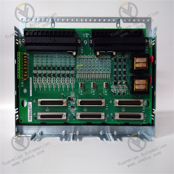
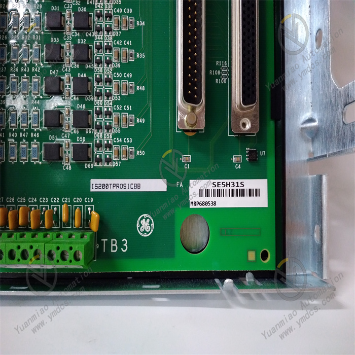
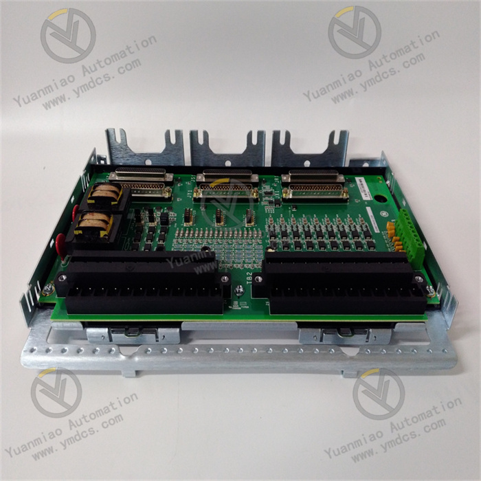
GE IS200TPROS1CBB
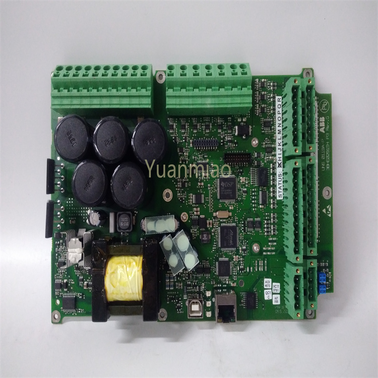
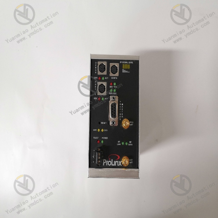
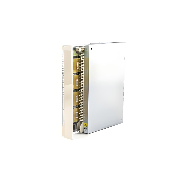
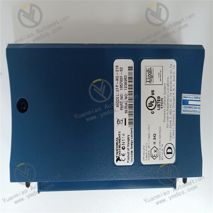
The GE IS200TPROS1CBB is a process I/O module belonging to the Mark VIe turbine control system. Its core positioning is an "integrated acquisition and control unit for process parameters and switch signals of turbine equipment". Its core value lies in integrating the scenario-specific design of GE turbine control and high-reliability hardware technology, providing a full-link solution of "multi-type analog quantity acquisition (pressure/flow/liquid level) + digital input/output + process interlock control" for the operation process of gas turbines and steam turbines.
Compared with general industrial I/O modules, it focuses more on "turbine scenario adaptability" — it supports 4-20mA analog input (compatible with pressure/flow transmitters), 0-10V analog output (controlling valve positioners), and 24V DC digital input/output (monitoring valve status/controlling pump sets). Meanwhile, it holds SIL 2 safety certification (IEC 61508) and has the ability to withstand high vibration (≤5g) and high temperature (ambient temperature ≤65℃), enabling stable operation under the harsh working conditions of high electromagnetic interference and high mechanical vibration in turbines. By collaborating with the Mark VIe controller and temperature modules (such as IS200TTURH1CFD), it realizes full-dimensional monitoring of turbines covering "temperature + process parameters + switch status". When process parameters exceed limits (e.g., excessively low lubricating oil pressure), it can trigger an interlock signal within ≤15ms, preventing faults such as wear and shutdown of turbine equipment caused by abnormal process parameters. It is a key component for "full operating condition control" of turbine equipment in industries such as power generation, petrochemicals, and aerospace.
As a core process I/O unit of the Mark VIe control system, this module supports seamless integration with GE turbine controllers (TCIA/TCIB) and HMI. It is compatible with general communication protocols such as Modbus TCP and OPC UA, balancing the professionalism of turbine control and the flexibility of system integration, and providing process signal support for "predictive maintenance" and "closed-loop control" of turbine equipment.
- Integration of Multiple Signal Types: The configuration of 16 AI channels (for collecting pressure/flow/liquid level) + 8 AO channels (for controlling valves/inverters) + 16 DI channels (for monitoring valve status/emergency stop signals) + 8 DO channels (for controlling pump sets/alarming) can replace 2-3 general-purpose I/O modules, reducing the volume of the turbine control cabinet by 60% and lowering wiring complexity (e.g., signals such as lubricating oil pressure, fuel flow, and steam liquid level can be collected centrally).
- Turbine-Specific Signal Adaptation: AI channels default to supporting 4-20mA (compatible with turbine-commonly-used pressure transmitters, such as Rosemount 3051), AO channels have a load capacity of ≤750Ω (compatible with turbine valve positioners, such as Fisher DVC6200), and DI channels support 24V DC dry contacts (for monitoring turbine emergency stop buttons and valve open/close feedback), eliminating the need for additional signal conversion modules.
- High Accuracy and High Responsiveness: AI measurement accuracy of ±0.05% FS (ensuring fuel flow measurement error ≤0.1%) and DI response time of ≤1ms (capturing rapid triggering of turbine emergency stop signals) meet the control requirements of "high-precision monitoring + rapid interlocking" for turbine process parameters.
- High Vibration and High-Temperature Resistance: The 5g vibration resistance design adapts to mechanical vibration caused by high-speed rotation of turbine rotors (e.g., 3000rpm). The 0℃-65℃ operating temperature range covers high temperatures in turbine rooms in summer (≤60℃ without air conditioning). Components inside the module are fixed with anti-vibration glue and packaged with high-temperature resistance, ensuring no solder joint detachment or parameter drift during long-term operation.
- Resistance to Strong Electromagnetic Interference: Strong electromagnetic radiation generated by turbine generators and inverters can interfere with process signals. The module adopts a three-layer EMC design of "shielding grounding + signal filtering + photoelectric isolation", resulting in AI signal fluctuation ≤±0.02% FS and DI signal false trigger rate ≤0.01%, avoiding false interlocks caused by electromagnetic interference.
- Dual Redundancy Guarantee: Supports dual 24V DC power redundancy (switching time ≤10ms) and Mark VIe backplane bus redundancy. When the main power supply or communication link fails, the backup link switches seamlessly, ensuring uninterrupted collection of turbine process signals and meeting the safety requirement of "no single point of failure" for turbines.
- SIL 2 Safety Certification and Rapid Interlocking: Certified to IEC 61508 SIL 2, it supports composite interlock logic of "process parameters + switch status" (e.g., "lubricating oil pressure <0.2MPa AND oil level <20% → trigger shutdown"). The interlock signal takes ≤15ms from detection to output, much faster than the turbine safety shutdown requirement (≤100ms), preventing bearing burnout caused by insufficient lubricating oil in turbines.
- Fault Self-Diagnosis and Safe Output: Automatically detects AI channel disconnection/short circuit (e.g., displaying "Open Circuit" when a pressure transmitter is disconnected), DI channel overvoltage, and DO channel overcurrent. In case of faults, DO channels can be configured for "safe output" (e.g., AO output 4mA for valve control to close the fuel valve), and fault information is uploaded via LEDs and HMI to facilitate quick localization by maintenance personnel.
- Channel Isolation and Insulation Protection: AI/AO/DI/DO channels and the power supply adopt 2.5kVrms photoelectric isolation, with insulation resistance ≥100MΩ, preventing module damage caused by turbine equipment leakage or signal crosstalk and complying with the industrial safety electricity standard (EN 61140).
- Seamless Collaboration with Mark VIe System: As a native Mark VIe module, it can be directly inserted into standard racks and share controller resources with temperature modules (IS200TTURH1CFD). Process parameters and temperature data are uploaded to HMI synchronously, forming an integrated monitoring interface of "temperature-pressure-flow-status" (e.g., real-time curves of "rotational speed + fuel flow + bearing temperature" during turbine startup).
- General Communication and Data Traceability: Optional Modbus TCP and OPC UA protocols enable process data upload to plant DCS (e.g., Siemens PCS 7) or GE Predix cloud platform, supporting remote monitoring of turbine equipment (e.g., remotely viewing lubricating oil pressure trends) and predictive maintenance (e.g., analyzing nozzle wear through fuel flow changes).
- Visual Configuration and Debugging: I/O parameters (such as AI range, DI trigger mode, and interlock logic) can be configured graphically via GE ToolboxST software. It supports online monitoring of real-time values of each channel (e.g., current AI current, DO output status) and historical fault records (storage ≥1 year), allowing non-professional turbine engineers to complete basic configuration within 30 minutes.
A 300MW gas turbine requires monitoring of the fuel system (fuel pressure 0-1MPa, 4-20mA; fuel flow 0-100m³/h, 4-20mA) and lubricating oil system (lubricating oil pressure 0-0.5MPa, 4-20mA; lubricating oil level 0-100%, 4-20mA), controlling fuel valve opening (AO 4-20mA) and lubricating oil pump startup/shutdown (DO 24V DC), and monitoring valve status (DI 24V DC, valve open/close feedback). The module is required to operate stably in a gas turbine environment with high vibration (≤3g) and turbine room temperature of 30℃-60℃, and support linkage with the Mark VIe controller to realize overpressure/low liquid level interlocking.
- Process Signal Acquisition: Among the 16 AI channels, 4 are connected to fuel pressure/flow and lubricating oil pressure/level transmitters (4-20mA) to collect process parameters in real time (sampling rate 50 samples/second), ensuring accurate capture of fuel pressure fluctuations ≤±0.01MPa.
- Control and Interlocking: Among the 8 AO channels, 1 outputs 4-20mA to control fuel valve opening (e.g., reducing the opening when fuel pressure >0.8MPa); among the 8 DO channels, 2 control the startup/shutdown of the main/backup lubricating oil pumps; the interlock logic "lubricating oil pressure <0.2MPa OR oil level <20% → DO output to cut off the fuel valve + start the backup oil pump + upload shutdown signal" is configured.
- Status Monitoring: 16 DI channels are connected to the open/close feedback signals of fuel valves/lubricating oil valves. When the valve feedback is inconsistent with the control command (e.g., command is "open" but feedback is "closed"), an HMI alarm is triggered to avoid abnormal fuel supply caused by valve jamming.
A 6MW steam turbine in a petrochemical catalytic cracking unit requires monitoring of steam parameters (main steam pressure 8-12MPa, 4-20mA; main steam temperature 400-500℃, 4-20mA (converted via a temperature transmitter)) and the condensate system (condensate level 0-100%, 4-20mA; condensate pump outlet pressure 0-1MPa, 4-20mA), controlling steam inlet valve opening (AO 4-20mA) and condensate pump startup/shutdown (DO 24V DC). The module is required to operate in a catalytic workshop environment with high dust and strong electromagnetic interference (near inverters) and support communication with the S7-1500 DCS.
- Anti-Interference Acquisition and Control: AI channels collect steam pressure/temperature and condensate level/pressure signals. Input cables use shielded twisted pairs (single-end grounding of the shield layer), and the module is installed in a control cabinet ≥2m away from inverters, ensuring AI signal fluctuation ≤±0.02% FS; AO channels output 4-20mA to control steam valve opening with an accuracy of ±0.1% FS, meeting the requirements of steam flow regulation.
- DCS Communication and Monitoring: An optional Modbus TCP interface uploads process parameters (update frequency 1s) to the S7-1500 DCS. The DCS interface displays a linked curve of "steam pressure-temperature-flow". When steam pressure >12MPa, the DCS issues a command to the module, and the DO output cuts off the steam inlet valve.
- Dust Protection and Maintenance: IP20 protection prevents dust in the catalytic workshop from entering the terminals. The terminal block adopts an anti-oxidation gold-plated
![]()


