Description
GE IS200TVBAH2ABC
I. Product Overview
GE IS200TVBAH2ABC is a key analog input/output (I/O) module in the Mark VIe series digital control system for steam turbines. It is specifically designed for scenarios involving multi-channel analog signal acquisition, high-precision signal conversion, and reliable control command output during the operation of large-scale steam turbine generator units. It is widely used in fields with strict requirements for monitoring steam turbine operating parameters and control precision, such as thermal power generation, combined cycle power generation, and industrial captive power plants. As the "signal processing hub" of the Mark VIe system, this module integrates multi-channel analog input interfaces, high-precision analog output interfaces, redundant communication links, and online diagnostic units. It can seamlessly connect to sensors for temperature, pressure, flow rate, and liquid level of steam turbines, as well as actuators such as speed control valves and regulating valves. It also collaborates efficiently with the system's main control module (e.g., IS200VCMIH2CAA) to realize real-time monitoring and closed-loop control of key operating parameters of steam turbines, providing accurate signal support for the safe and stable operation of the unit.
II. Functional Features
- Multi-Channel High-Precision Signal AcquisitionEquipped with 16 analog input channels and 8 analog output channels, the input channels support multiple standard analog signal types including 4-20mA, 0-20mA, 0-5V, and 1-5V, which can be flexibly configured to adapt to signals from different sensors. It adopts a 16-bit high-precision AD conversion chip with a conversion accuracy of ±0.05% FS, and the sampling rate can be configured in grades within the range of 10Hz-1000Hz to meet the monitoring needs of different parameters—for slow-changing parameters such as temperature and liquid level, a low sampling rate can be selected to reduce system load; for fast-changing parameters such as pressure and flow rate, a high sampling rate can be chosen to ensure signal integrity. Each input channel has a built-in independent signal conditioning circuit, featuring overvoltage protection (±30V DC), overcurrent protection (≤50mA), and anti-aliasing filtering functions. These functions can effectively suppress on-site electromagnetic interference and ensure the stability and accuracy of collected signals. For example, the acquisition error of the main steam pressure of the steam turbine can be controlled within ±0.02MPa.
- High-Reliability Analog OutputEach of the 8 analog output channels uses a 16-bit DA conversion chip, with an output accuracy of ±0.1% FS. They support standard output signal types such as 4-20mA, 0-20mA, and 0-10V, and can directly drive actuators like speed control valves and regulating valves. The output channels are equipped with short-circuit protection and overload protection functions: when the output current exceeds 30mA, the module automatically cuts off the output and triggers an alarm, and the output can be automatically restored after the fault is eliminated. It adopts an "output hold" design—when communication between the module and the main control module is interrupted, the output channels can maintain the last valid control signal, preventing unit operation fluctuations caused by misoperation of actuators. The temperature drift coefficient of the output signal is ≤5ppm/℃, and within the operating temperature range of -10℃ to 65℃, the output deviation can be controlled within ±0.2% FS, ensuring the stability of control commands.
- Redundant Communication and Flexible CascadingIt uses a dual-channel Genius redundant bus as the main communication interface, combined with one standby EtherNet/IP interface, to achieve high-speed data interaction with the main control module and other I/O modules. The communication rate of the Genius bus reaches 1Mbps, and the data transmission delay is ≤2ms. The redundant communication links have an automatic switching function: when the main link experiences communication interruption or a packet loss rate ≥1%, it can switch to the standby link within 1ms to ensure uninterrupted signal transmission. It supports the "master-slave" cascading mode—a single main control module can cascade 8 IS200TVBAH2ABC modules, and realize inter-module data sharing through the Genius bus. This can be expanded to 128 analog input channels and 64 analog output channels, meeting the centralized control needs of large-scale units with multiple measurement points and multiple actuators. The module supports hot-swapping, allowing replacement and maintenance of the module without shutting down the system, which significantly reduces the risk of unplanned downtime.
- Full-Dimensional Self-Diagnosis and Fault Early WarningA three-level self-diagnosis system ("channel-level - module-level - link-level") is built, with a diagnostic coverage rate of 99.9%. Channel-level diagnosis monitors the signal status of each input/output channel in real time—when an input signal exceeds the range, an output signal deviation exceeds the threshold, or a channel is short-circuited, the faulty channel is immediately marked and an alarm is triggered. Module-level diagnosis performs a self-check every 10ms to monitor the working status of core components such as power supply voltage, AD/DA conversion unit, and communication chip; if a chip fault or power supply abnormality (e.g., input voltage lower than 19V DC) is detected, a fault signal is promptly output. Link-level diagnosis monitors the connection status with the main control module through communication check codes and records fault information such as communication interruptions and packet loss. Diagnostic information can be displayed locally through the LED indicators on the front panel of the module, and can also be uploaded to the main control module and upper-level operation and maintenance platform via communication links. It supports the storage of 1000 fault logs, each containing the faulty channel, fault type, and occurrence time, facilitating quick location and troubleshooting by operation and maintenance personnel.
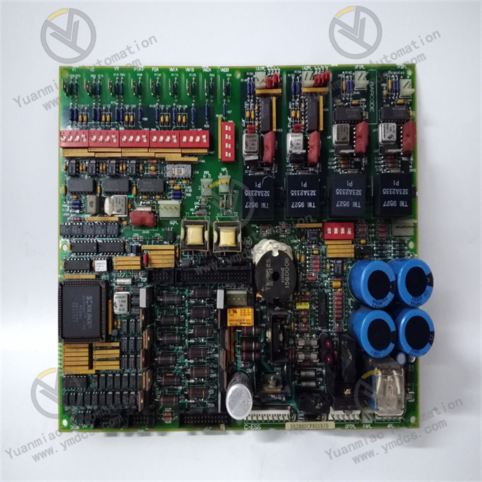
- Wide-Range Environmental Adaptability and Modular DesignIt has excellent environmental adaptability, with an operating temperature range of -10℃~65℃, a storage temperature range of -40℃~85℃, and a relative humidity of 5%~95% (no condensation). It can adapt to power plant environments in different regions such as high altitude and high humidity, and meets the requirements of standards like GB/T 14537-1993 Impact and Shock Tests for Measuring Relays and Protection Devices. It adopts 35mm standard rail mounting, with dimensions of 160×180×85mm and a compact structure. A spacing of ≥5mm between adjacent modules can meet heat dissipation requirements, adapting to the installation layout of mainstream control cabinets. The module adopts a modular split design—the signal conditioning unit, conversion unit, and communication unit can be independently disassembled and replaced, reducing maintenance costs. The front panel is equipped with 16 input status LEDs, 8 output status LEDs, and 2 communication status LEDs, which can intuitively display the operating status of each channel and the module, facilitating quick on-site inspection.
- Convenient Configuration and Calibration ManagementIt supports full-parameter configuration through GE ControlST V7.0 and above configuration software. The software provides a graphical configuration interface, allowing intuitive setting of parameters such as signal type, sampling rate, and alarm threshold for input/output channels. It has a built-in channel parameter copying function, enabling quick unified configuration of multiple channels. It is equipped with an online calibration function—by issuing calibration commands through the configuration software, zero-point and full-scale calibration of input/output channels can be performed without disassembling the module, and the calibration accuracy can be traced to national metrology standards. It supports batch import and export of parameters, facilitating unified configuration and backup of multiple modules and significantly shortening the debugging cycle.
III. Technical Parameters
| Parameter Category | Parameter Name | Specific Parameters | Unit |
|---|---|---|---|
| Basic Parameters | Model | GE IS200TVBAH2ABC | - |
| Module Type | Analog Input/Output (I/O) Module | - | |
| Overall Dimensions (L×W×H) | 160×180×85 | mm | |
| Weight | Approximately 1.2 | kg | |
| Analog Input Parameters | Number of Input Channels | 16 channels (independent channels, configurable individually) | Channel |
| Supported Signal Types | 4-20mA, 0-20mA, 0-5V, 1-5V DC | - | |
| AD Conversion Accuracy | 16-bit, ±0.05% FS | - | |
| Sampling Rate | 10Hz-1000Hz, configurable in grades | Hz | |
| Input Impedance | Current signal: ≤100Ω; Voltage signal: ≥1MΩ | Ω | |
| Overvoltage Protection | ±30V DC, automatic recovery | V DC | |
| Analog Output Parameters | Number of Output Channels | 8 channels (independent channels, configurable individually) | Channel |
| Supported Signal Types | 4-20mA, 0-20mA, 0-10V DC | - | |
| DA Conversion Accuracy | 16-bit, ±0.1% FS | - | |
| Output Load Capacity | Current signal: ≤500Ω; Voltage signal: ≥10kΩ | Ω | |
| Overcurrent Protection | ≤30mA, automatic cut-off and alarm, recovery after fault elimination | mA | |
| Temperature Drift Coefficient | ≤5ppm/℃ | ppm/℃ | |
| Power Supply Parameters | Power Supply Mode | DC power supply, supporting redundant backup | - |
| Input Voltage Range | DC 24V±15% (19.2-27.6V DC) | V DC | |
| Rated Supply Current | ≤0.8A (full load) | A | |
| Power Supply Ripple Rejection Ratio | ≥60dB (100Hz-1MHz) | dB | |
| Communication Parameters | Standard Communication Interfaces | 2-channel Genius redundant bus, 1-channel standby EtherNet/IP interface | - |
| Supported Protocols | Genius, EtherNet/IP | - | |
| Communication Rate | Genius bus: 1Mbps; EtherNet/IP: 100Mbps | bps | |
| Data Transmission Delay | ≤2ms | ms | |
| Cascading Quantity | Up to 8 modules in cascade | Unit | |
| Environmental & Reliability Parameters | Operating Temperature Range | -10~65 | ℃ |
| Storage Temperature Range | -40~85 | ℃ | |
| Relative Humidity | 5%~95% (no condensation) | % | |
| Protection Class | IP20 | - | |
| Vibration Resistance | 5-200Hz, 1.0g acceleration (IEC 60068-2-6) | - | |
| Mean Time Between Failures (MTBF) | ≥300,000 | Hour | |
| Diagnostic Parameters | Diagnostic Coverage Rate | 99.9% | - |
| Fault Log Storage | 1000 logs, including faulty channel, type, and time | Log |
IV. Working Principle
As an analog I/O module for the steam turbine control system, the working principle of GE IS200TVBAH2ABC revolves around six core links: "signal acquisition - signal conditioning - conversion calculation - data transmission - command output - diagnostic feedback". Through high-precision signal processing and redundant communication mechanisms, it achieves efficient collaboration with the main control module and precise control of on-site equipment. The specific process is as follows:
- Power Supply and Signal Preprocessing LinkAfter 24V DC power is connected through the module's power interface, it first passes through an EMC filter circuit and a surge suppression circuit to filter out high-frequency interference and instantaneous surge signals in the power grid, ensuring stable input power. Then, it outputs precise voltages such as 5V and 3.3V through the DC-DC conversion unit to supply power to the signal conditioning unit, AD/DA conversion unit, communication unit, etc., with an output ripple of ≤5mV to ensure stable operation of each unit. At the same time, the power monitoring circuit monitors the input voltage and the module's operating current in real time—when the voltage is lower than 19.2V or higher than 27.6V, or the current exceeds 1A, it immediately triggers a power fault alarm and uploads it to the main control module.
- Analog Input Acquisition and Processing LinkAnalog signals output by on-site sensors (e.g., pressure sensors, temperature transmitters) are connected to the 16 input channels of the module via shielded cables, and each channel corresponds to an independent signal conditioning circuit. For current signals, the conditioning circuit first converts them into standard voltage signals, then filters out high-frequency noise through an anti-aliasing filter circuit; for voltage signals, they are directly processed by the filter circuit and then enter the gain adjustment unit, where the signal amplitude is adjusted to the optimal input range of the AD conversion unit according to configuration parameters. The processed signals are sent to the 16-bit AD conversion chip to convert analog signals into digital signals. The converted digital signals are temporarily stored in the module's buffer, which can store 100 sets of historical data for the main control module to read. During the sampling process, the clock synchronization circuit ensures that the sampling time of each channel is consistent, avoiding data deviation caused by signal delay between channels.
- Data Transmission and Main Control Collaboration LinkThe module establishes a communication link with the main control module through a dual-channel Genius redundant bus, and the main link is used for data transmission by default. After the digital signals in the buffer are encapsulated by the communication protocol, they are uploaded to the main control module according to the preset sampling cycle, while receiving configuration commands (e.g., sampling rate adjustment, channel parameter modification) issued by the main control module. During communication, the link monitoring circuit verifies the integrity of data frames in real time—if packet loss or interruption occurs in the main link, it immediately switches to the standby link, with a switching time of ≤1ms to ensure uninterrupted data transmission. When communication between the module and the main control module is interrupted for more than 500ms, the output channels automatically trigger the "hold" mode to maintain the last valid output signal, preventing misoperation of actuators.
- Control Command Conversion and Output LinkAfter receiving the control commands issued by the main control module via the communication link, the command parsing unit first parses the command content to determine the target output channel, output signal type, and amplitude. The parsed commands are sent to the 16-bit DA conversion chip to convert digital control commands into analog signals. The converted analog signals are amplified by the output drive circuit and then output to actuators (e.g., speed control valves, regulating valves) through 8 output channels. During the output process, the feedback monitoring circuit collects the actual value of the output signal in real time and compares it with the command value—if the deviation exceeds ±0.1% FS, it immediately adjusts the DA conversion output and records the deviation information; if a short circuit or overload of the output is detected, the drive circuit immediately cuts off the output and triggers a fault alarm, and the output is automatically restored after the fault is eliminated.
- Full-Link Diagnosis and Feedback LinkThe module performs three-level diagnosis in real time: ① Channel-level diagnosis: Each input channel monitors the signal amplitude in real time—when the signal exceeds ±10% of the configured range, it is marked as an over-range fault; each output channel monitors the output current/voltage—when a short circuit, overload, or deviation exceeding the threshold occurs, it is marked as an output fault. ② Module-level diagnosis: A self-check is performed every 10ms to monitor the working status of core components such as the AD/DA conversion chip, communication chip, and buffer unit—if a non-responsive chip or data read/write error is detected, it is marked as a module hardware fault. ③ Link-level diagnosis: The connection status with the main control module is monitored through communication check codes, and the packet loss rate is counted every 100ms—when the packet loss rate is ≥1%, it is marked as a communication link fault. All diagnostic information is displayed locally through the LED indicators on the module (a red light indicates a fault, and a green light indicates normal operation), and is also uploaded to the main control module and upper-level platform via communication links. Fault logs are stored in chronological order with timestamps, supporting traceability and query.