Description
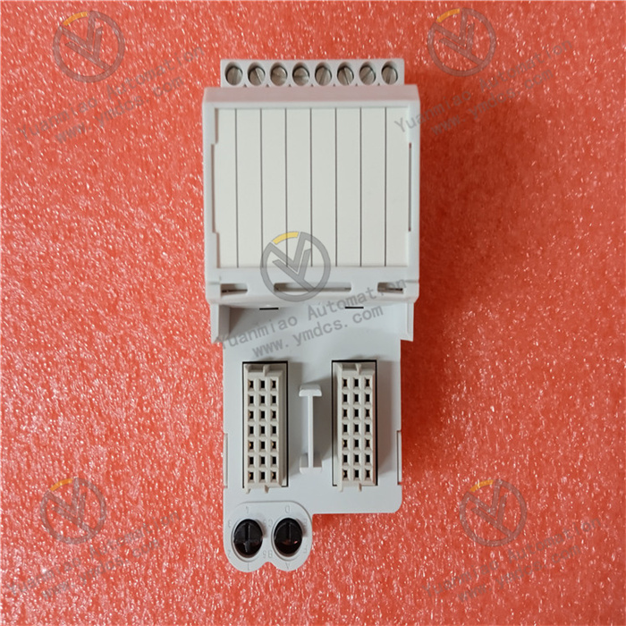
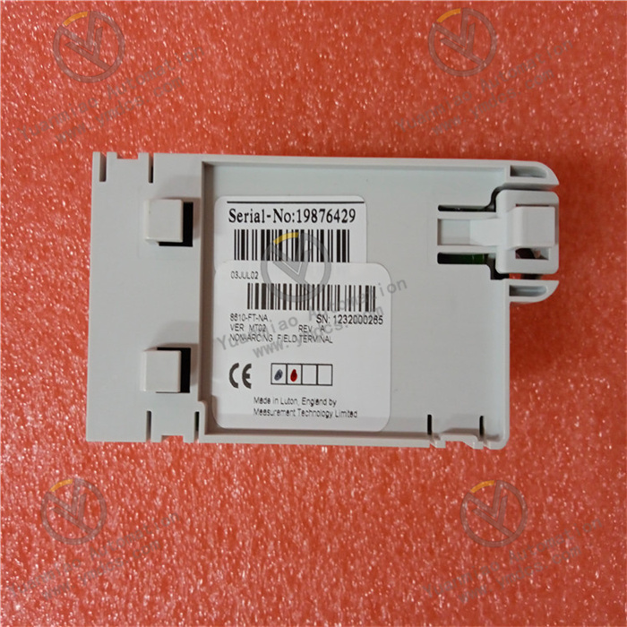
GE 8810-FT-NA
I. Overview
The GE 8810-FT-NA is a high-precision intelligent flow transmitter developed to meet the requirements of "accurate fluid flow measurement + real-time monitoring and control" in industrial processes. It belongs to the GE 8800 series of industrial measurement products. Its core positioning is to measure and transmit data of fluids (such as oil, chemical solvents, cooling water) and gases (such as compressed air, natural gas, process exhaust gas) in industrial pipelines, undertaking the integrated functions of "flow signal collection + data processing + remote communication + abnormal early warning".
The transmitter adopts a "flange-mounted structure + corrosion-resistant sensor probe" design. The components in contact with fluids are made of 316L stainless steel (Hastelloy C-276 is also an option), with an IP67 protection rating, enabling stable operation in a wide temperature range from -40°C to +85°C. Meanwhile, it has passed the IEC 61010-1 electrical safety certification, IEC 61326-1 EMC certification, and ATEX Zone 2 explosion-proof certification. It can resist dust erosion, high-pressure spraying, strong electromagnetic interference (such as inverter harmonics), and slightly corrosive fluids (such as weak acid solutions) in industrial sites, providing triple guarantees of "high precision + high reliability + explosion-proof safety" for fluid flow measurement.
II. Technical Parameters
| Parameter Category | Specific Specifications | Remarks |
|---|---|---|
| Core Measurement Parameters | Measurement Type: Differential pressure type (built-in high-precision differential pressure sensor) | Based on Bernoulli's principle, compatible with throttling devices such as orifice plates, Venturi tubes, and V-cones |
| Flow Measurement Range: 0.1-1000 m³/h (liquid), 1-10000 Nm³/h (gas) | Range can be adjusted via software calibration, with a turndown ratio of 1:100 | |
| Measurement Accuracy: ±0.15% Full Scale (FS) for liquids, ±0.2% FS for gases | Repeatability ≤ 0.05% FS to ensure long-term measurement stability | |
| Pressure Range: Rated working pressure 0-10 MPa, maximum pressure resistance 15 MPa | Suitable for medium and high-pressure industrial pipelines (e.g., oil transmission pipelines, process reactor feed pipes) | |
| Temperature Range: Medium temperature -50°C to +200°C (standard model); optional low/high-temperature models -196°C to +400°C | Compatible with normal-temperature, low-temperature (e.g., LNG), and high-temperature (e.g., steam) fluid measurement | |
| Electrical Characteristics | Power Supply Voltage: DC 24V ±15%, or AC 220V ±10% (optional) | Low-power design, rated power consumption ≤ 1.5W when powered by DC 24V |
| Output Signal: DC 4-20mA (2-wire/4-wire optional), HART 7.0 protocol, Modbus RTU | The 4-20mA signal has a linear correspondence with the flow range; HART protocol supports remote parameter configuration and diagnosis | |
| Communication Interface: RS485 (Modbus RTU), configurable communication rate 1200-115200 bps | Supports data interaction with Programmable Logic Controllers (PLC), DCS, and remote monitoring terminals | |
| Physical & Environmental Characteristics | Housing Material: Aluminum alloy (with anti-corrosion powder coating), sensor contact material 316L stainless steel | Housing impact resistance: 10 kJ/m²; sensor resistant to acid and alkali corrosion (compliant with NACE MR0175 standard) |
| Installation Method: Flange mounting (suitable for DN15-DN2000 pipelines), or threaded mounting (suitable for small-diameter DN15-DN50 pipelines) | Flange standards comply with ANSI B16.5, GB/T 9119, etc., suitable for different industrial pipeline specifications | |
| Protection Rating: IP67 (standard model); optional IP68 (submersible model for underwater pipelines) | Fully dust-proof and resistant to short-term immersion (30 minutes at 1m water depth), suitable for humid and dusty on-site environments | |
| Weight: Approximately 3.5 kg (DN50 flange model, excluding throttling device) | Lightweight design for easy installation and maintenance on pipelines |
III. Functional Features
1. Wide-Range and High-Precision Flow Measurement
2. Multi-Parameter Integrated Monitoring and Intelligent Compensation
3. Flexible Communication and System Integration Capability
4. Full-Scenario Protection and High-Reliability Design
5. Convenient Operation & Maintenance and Safety Early Warning Function
IV. Common Faults and Solutions
| Fault Phenomenon | Possible Causes | Solutions |
|---|---|---|
| 1. No output signal from the transmitter, and the power indicator is off | 1. Power supply line disconnection or loose terminal connections; 2. Power supply voltage out of range (e.g., DC 24V lower than 18V); 3. Damaged internal power module; 4. Damaged explosion-proof sealing gasket causing water ingress and short circuit | 1. Use a multimeter to check the continuity of the power supply line, inspect the terminals (e.g., "+" and "-" poles), re-tighten them, and ensure correct wiring; 2. Measure the power supply voltage; if the voltage is too low, inspect the external power supply (e.g., switching power supply failure) and replace it with a power supply of ≥5W that meets the DC 24V ±15% specification; 3. If there is still no output with normal power supply, contact GE-authorized maintenance personnel to inspect the internal power chip (e.g., TI TPS7A4700) and replace damaged components; 4. Inspect the explosion-proof sealing gasket; if damaged, replace it with a gasket of the same specification (GE original parts are recommended), and open the cover to clean internal water in a safe environment |
| 2. Large deviation in flow measurement value, exceeding the accuracy range | 1. Incorrect installation of the throttling device (e.g., reversed orifice plate, insufficient straight pipe sections before and after); 2. Sensor zero drift; 3. Temperature/pressure compensation not enabled (e.g., no pressure compensation for gas flow); 4. Fluid cavitation or turbulence (e.g., no flow straightener after pipeline elbows) | 1. Verify the installation specifications of the throttling device (e.g., the "+" mark of the orifice plate faces the fluid flow direction, with straight pipe sections ≥10D before and ≥5D after, where D is the pipeline diameter), and readjust the installation position; 2. Perform zero calibration via a HART handheld communicator or software (ensure the fluid in the pipeline is stationary and close the upstream and downstream valves); 3. Check the compensation parameter configuration, enable automatic temperature/pressure compensation, and input basic parameters such as fluid density and compressibility factor with reference to the fluid property manual; 4. Install a flow straightener in turbulent pipeline areas (e.g., elbows, pump outlets) or adjust the transmitter installation position to a straight pipe section to reduce fluid disturbance |
| 3. Frequent fluctuation of the output signal, unstable flow display | 1. Fluid pulsation in the pipeline (e.g., no buffer device at the reciprocating pump outlet); 2. Electromagnetic interference on the signal line (e.g., close to inverters or motors); 3. Unreasonable digital filtering parameter settings (e.g., too short filtering time); 4. Blockage of the sensor differential pressure detection chamber (e.g., fluid impurities, scaling) | 1. Install a pulsation buffer at the pump outlet or a damper before the transmitter to reduce fluid pulsation; 2. Replace the signal line with twisted-pair cables with double shielding, ground one end of the shield (near the transmitter), and keep the signal line at a distance of ≥1m from strong interference sources (e.g., inverters, motors); 3. Adjust the digital filtering time via a HART handheld communicator (it is recommended to gradually increase it from 1s to 5s and observe signal stability); 4. Close the upstream and downstream valves, disassemble the transmitter, and purge the differential pressure detection chamber with high-pressure nitrogen (0.5 MPa); if scaling is severe, soak and clean it with a neutral cleaning agent (e.g., isopropyl alcohol), taking care not to damage the sensor diaphragm |
| 4. HART communication interruption, unable to configure parameters remotely | 1. Incorrect communication parameters of the HART handheld communicator/software (e.g., mismatched baud rate); 2. Poor contact or disconnection of the communication line; 3. Faulty HART module of the transmitter; 4. Short circuit or ground fault in the 4-20mA line | 1. Verify the HART communication parameters (default baud rate 1200 bps, default address 0) and ensure the parameters of the handheld communicator/software match those of the transmitter; 2. Use a multimeter to check the continuity of the HART communication line (4-20mA positive and negative poles), inspect the terminals for looseness, and repair broken points; 3. Test with a spare HART handheld communicator; if communication still fails, contact maintenance personnel to inspect the HART module (e.g., ADI AD5700 chip) and replace faulty components; 4. Measure the insulation resistance of the 4-20mA line (required to be ≥10 MΩ), eliminate short circuit or ground faults, and replace the shielded cable if the line is damaged |
| 5. Transmitter alarm light flashing, displaying "Sensor Overload" fault | 1. Sudden increase in pipeline pressure exceeding the rated working pressure; 2. Excessively small range of the differential pressure sensor; 3. Damaged sensor diaphragm (e.g., impact, corrosion); 4. Faulty internal signal processing circuit | 1. Measure the pipeline pressure with a pressure gauge; if overpressure occurs, inspect upstream equipment (e.g., closed pump outlet valve) and reduce the pipeline pressure to the rated range; 2. Verify whether the sensor range matches the actual differential pressure range (e.g., an actual differential pressure of 10 kPa with a 5 kPa range will cause overload), and reconfigure an appropriate range via a HART handheld communicator; 3. Disassemble the transmitter to inspect the sensor diaphragm; if damaged or corroded, have GE-certified engineers replace the sensor assembly; 4. If the pressure and range are normal, inspect the internal signal processing circuit (e.g., amplifier chip) and replace faulty components |


