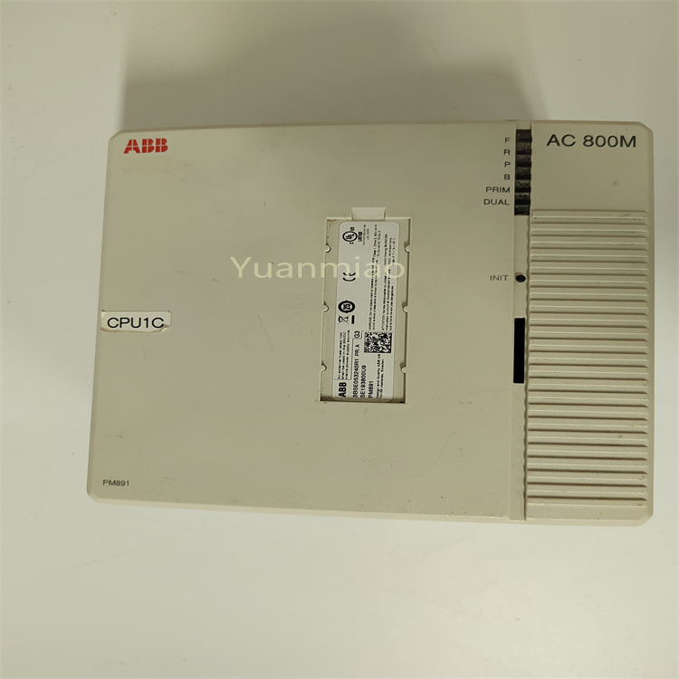
Description
GE IS200WETBH1ABA
1. Overview
The GE IS200WETBH1ABA is an Ethernet communication and signal conversion module developed for industrial gas turbine control systems. Its core positioning is a "networked data interaction hub for gas turbine control systems", and it mainly serves industries such as power generation (e.g., F-class/H-class gas turbines in combined cycle power plants), petrochemicals (e.g., gas turbine-driven compressors in oil refineries), and energy (e.g., gas turbine waste heat power stations). It is a core component in the GE Speedtronic Mark VIe gas turbine control system, enabling high-speed data interaction between controllers, I/O modules, on-site intelligent devices (such as smart sensors and actuators), and upper-level monitoring systems (SCADA/MES).
2. Technical Specifications
2.1 Core Communication Parameters
Ethernet Port Configuration
- Number of Ports: 2 Gigabit Ethernet electrical ports (RJ45 interface), supporting dual-network redundancy (active-standby switchover) or link aggregation (bandwidth enhancement) modes.
- Communication Rate: 10/100/1000Mbps auto-negotiation, supporting full-duplex/half-duplex modes (full-duplex by default).
- Transmission Distance: ≤ 100m (Cat 5e or above unshielded twisted pair); can be extended to 10km (single-mode fiber) via fiber optic transceivers.
- Network Topology: Supports star and ring topologies (ring network management protocol required for ring topology); ring network self-healing time ≤ 20ms (faulty node switchover).
Protocol Compatibility and Conversion
- Supported Protocols:
- Industrial Ethernet protocols: Profinet IO (IRT real-time mode), EtherNet/IP (CIP Sync), Modbus-TCP;
- Traditional bus protocols (external gateway required): Modbus-RTU (RS485), Profibus-DP;
- GE-specific protocols: Genius Bus, SRTP (Speedtronic Real-Time Protocol).
- Protocol Conversion Capability: Supports bidirectional data conversion between different protocols (e.g., Profinet IO to Modbus-TCP), with conversion latency ≤ 1ms and data throughput ≥ 1000 frames/second (100 bytes per frame).
Communication Performance
- Real-Time Performance: In Profinet IO IRT mode, cycle time ≤ 1ms, jitter ≤ 10μs; in EtherNet/IP CIP Sync mode, time synchronization accuracy ≤ 1μs (IEEE 1588 PTP v2).
- Reliability: Packet loss rate ≤ 0.001% (when network load ≤ 80%), bit error rate ≤ 1×10⁻⁹, supporting data retransmission and verification (CRC32).
2.2 Physical and Environmental Parameters
Physical Specifications
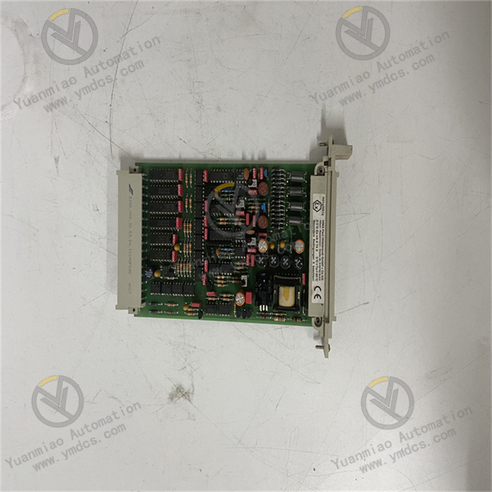
- Dimensions: 220mm (length) × 160mm (width) × 80mm (height) (including mounting clips). Adopting the standard rack slot design of the GE Mark VIe system, it can be directly inserted into the I/O rack of the Mark VIe control cabinet. It is dimensionally compatible with modules of the same series (e.g., IS200SAMBH1ABA, IS200STAOH2AAA), allowing mixed installation in the cabinet to simplify layout.
- Weight: Approximately 1.0kg. The modular design supports insertion and removal by a single person, with a replacement time ≤ 5 minutes (equipped with quick-connect terminals).
- Interface Terminals: 2 RJ45 Ethernet ports (with LED status indicators), 1 RS485 auxiliary communication port (for protocol conversion configuration), 1 USB debugging port (for local parameter configuration).
Environmental Adaptability
- Operating Temperature: -40℃~+70℃, meeting the operational requirements of high-temperature gas turbine rooms (up to 55℃ in poorly ventilated conditions in summer) and outdoor control cabinets in cold regions (-35℃ in winter). No preheating is required for low-temperature startup (-40℃), and the startup time is ≤ 30s.
- Humidity: 5%~95% (non-condensing, complying with IEC 60068-2-3 standard). In the high-humidity environment of coastal power plants, the circuit board shows no corrosion or leakage.
- Protection Rating: IP20 (for installation inside control cabinets), compatible with the overall IP54 protection system of the Mark VIe control cabinet, preventing dust from entering the module interior.
Vibration and Shock Resistance: Vibration resistance rating of 10g (10Hz~2000Hz, complying with IEC 60068-2-6), capable of withstanding continuous vibration during gas turbine operation; shock resistance rating of 20g (11ms pulse, complying with IEC 60068-2-27), capable of withstanding shock loads during unit startup and shutdown.
- Electromagnetic Interference (EMI) Resistance: Complies with the EN 61000-6-2 industrial immunity standard. Electrostatic Discharge (ESD) protection: ±15kV (air discharge)/±8kV (contact discharge); radio frequency radiation immunity: 10V/m (80MHz~1GHz). In high-interference environments such as near generators and high-voltage cables, the communication interruption time is ≤ 10ms (automatic recovery).
2.3 Power Supply and Reliability Parameters
- Power Supply Requirements: Operating voltage: 24V DC (wide-range adaptation: 18V DC~36V DC), powered by the backplane of the Mark VIe system rack. Operating current ≤ 300mA (when dual network ports are fully loaded), power consumption ≤ 7.2W, without increasing the power supply load of the cabinet.
- Isolation Performance: Electrical isolation between Ethernet ports, power supply, and RS485 ports, with an isolation voltage ≥ 2500Vrms for 1 minute. Common Mode Rejection Ratio (CMRR) ≥ 100dB (50Hz), effectively blocking ground loop interference and common-mode noise.
Reliability Indicators: Mean Time Between Failures (MTBF) ≥ 400,000 hours (per Telcordia SR-332 standard at 25℃), design life ≥ 20 years. Key components (e.g., Ethernet chips, power management chips) are selected from military-grade products, and the module supports "dual-network port redundancy" (when the active network port fails, the standby network port automatically switches within 10ms).
- Management and Configuration: Supports three configuration methods: Web browser configuration (accessing the module's IP address via Ethernet port), GE ControlST configuration software, and USB local configuration. Configuration parameters support backup and restoration (in XML format).
3. Functional Features
3.1 Highly Reliable Ethernet Communication and Redundancy
- Dual-Network Port Redundancy and Self-Healing: The 2 Ethernet ports support the "active-standby redundancy" mode. When the active port is normal, the standby port is in a listening state (real-time data synchronization); when the active port detects a link interruption (e.g., network cable disconnection, switch failure), the standby port automatically takes over communication within 10ms without losing data frames (buffer ≤ 100 frames). For example, in the control of gas turbines in combined cycle power plants, when the active network port is interrupted due to a switch failure, the standby port switches quickly, ensuring uninterrupted communication between the controller and intelligent actuators (such as guide vane actuators) and avoiding unit load fluctuations.
Ring Network Topology and Fast Self-Healing: Supports ring topologies such as Profinet ring network and EtherNet/IP device network. When a node (e.g., other communication modules) or link in the ring network fails, the module automatically calculates an alternate path through the ring network management protocol, with a self-healing time ≤ 20ms, ensuring the connectivity of the entire control network. In multi-unit cluster control (e.g., 3 gas turbines operating in parallel), the ring network topology can significantly improve network reliability, reducing the fault impact range from "full unit shutdown" to "single module offline".
Time Synchronization and Real-Time Communication: Supports the IEEE 1588 PTP v2 precision time synchronization protocol. When acting as a slave clock, the time synchronization accuracy with the master clock (e.g., Mark VIe controller) is ≤ 1μs; when acting as a master clock, it can synchronize up to 32 slave devices. In scenarios involving synchronous acquisition of multiple gas turbine parameters (such as bearing temperature, vibration, and rotational speed), precise time synchronization ensures the consistency of timestamps for data collected by various devices, providing an accurate time benchmark for data analysis (e.g., correlation analysis between temperature and vibration). Meanwhile, in Profinet IO IRT real-time mode, the cycle time can be as low as 1ms, meeting the millisecond-level response requirements for fuel valve adjustment and rotational speed control.
3.2 Multi-Protocol Compatibility and Flexible Conversion
- Full-Scenario Protocol Coverage: Compatible with industrial Ethernet, traditional buses, and GE-specific protocols, enabling connection to devices from different manufacturers without additional gateways. For example, in the control of gas turbines in oil refineries, the module can simultaneously connect to:
- GE Mark VIe controller (SRTP protocol);
- Siemens smart pressure sensor (Profinet IO protocol);
- Rockwell smart actuator (EtherNet/IP protocol);
- Third-party temperature data logger (Modbus-RTU protocol, connected via RS485 port);
This realizes centralized data interaction among all devices, simplifies the system architecture, and reduces integration costs (eliminating multiple gateway devices, saving approximately 50,000 yuan/set). Bidirectional Protocol Conversion and Data Mapping: Supports bidirectional data conversion between different protocols, and allows custom data mapping rules through configuration software (e.g., converting the "pressure value" (32-bit floating-point number) of a Profinet IO device into an "integer pressure value" (magnified by 100 times) in a Modbus-TCP register). For example, converting the "80.5℃" data from a third-party Modbus-RTU temperature sensor into the Profinet IO format and transmitting it to the Mark VIe controller, while converting the "50% fuel valve opening" command issued by the controller (in Profinet IO format) into the Modbus-TCP format and sending it to the smart fuel valve actuator, enabling cross-protocol control.
Data Filtering and Priority Scheduling: Supports data type-based filtering and priority scheduling. "Control commands" (such as actuator adjustment signals) can be configured as the highest priority (Priority 1), and "status monitoring data" (such as ambient temperature) as low priority (Priority 4). When the network load is too high (≥ 90%), the transmission of high-priority data is prioritized, with a packet loss rate ≤ 0.01%. During the gas turbine startup phase (intensive data interaction, including startup commands, rotational speed feedback, ignition signals, etc.), priority scheduling ensures that key control commands are not lost, avoiding startup failure.
3.3 Industrial-Grade Reliability and Intelligent Operation & Maintenance
- Extreme Environment Protection Design: The internal circuit board is coated with "nano-level three-proof paint + Teflon coating", providing triple protection against oil pollution, dust, and corrosion. In the high-oil-pollution and high-dust environment of gas turbine rooms, the circuit board shows no oil accumulation or component corrosion after 5 years of continuous operation. The housing is made of magnesium-aluminum alloy (lightweight and with good thermal conductivity). When the module operating temperature reaches 70℃, the internal component temperature remains ≤ 85℃ (lower than the rated temperature of 125℃), ensuring the stable operation of key components such as Ethernet chips and power chips.
Comprehensive Fault Diagnosis and Early Warning: Built-in network status monitoring and fault diagnosis functions, capable of identifying 15 types of faults such as "link interruption", "protocol mismatch", "IP address conflict", and "port overload". Alarms are issued through three methods:
- Module LED indicators (e.g., the "Link/Act" light stays red to indicate link interruption);
- The Ethernet port sends alarm frames to the controller, displaying fault codes on the HMI (e.g., "E12 = Active Network Port Link Interruption");
- Sending Modbus alarm commands to on-site audible and visual alarms via the RS485 port;
At the same time, it records the fault occurrence time and network parameters (such as packet loss rate and latency) before the fault, facilitating maintenance personnel to quickly locate the problem (reducing troubleshooting time from 2 hours to 30 minutes). Remote Operation & Maintenance and Status Monitoring: Supports remote access to the module via a Web browser (by entering the module's IP address) to view real-time operating status (such as dual-network port connection status, protocol conversion throughput, and CPU usage) and historical fault records (latest 50 entries); supports remote parameter configuration (such as modifying IP address and protocol conversion rules) and firmware upgrade (uploading firmware files via HTTP) without on-site cabinet opening operations. In power stations in remote areas (e.g., gas turbine power stations on the western plateau), remote operation and maintenance can significantly reduce the frequency of on-site inspections (from once a month to once a quarter), lowering maintenance costs and personnel safety risks.
3.4 In-Depth Adaptation to Gas Turbine Control
- Seamless Integration with Control Systems: As a native module of the Mark VIe system, it is deeply adapted to the hardware and software of controllers and I/O modules. In terms of hardware, it can be directly inserted into the Mark VIe rack and communicates with the controller at high speed via the backplane bus (data transmission rate 100Mbps, latency ≤ 1ms); in terms of software, module parameters (such as network mode and protocol conversion rules) can be directly configured through the ControlST configuration software, and the parameters are linked with the controller project file (the module automatically loads the configuration when the controller restarts), eliminating the need for separate debugging.
Secure Communication and Data Encryption: Supports secure communication mechanisms such as Profinet IO Security (PROFIenergy) and EtherNet/IP Security (CIP Security). Through digital certificate authentication, data encryption (AES-256), and Access Control List (ACL), it prevents unauthorized device access (e.g., counterfeit sensor data by hackers) and data tampering (e.g., malicious modification of fuel valve adjustment commands). In scenarios with high safety requirements such as gas turbines supporting nuclear power plants, secure communication can meet the IEC 61508 SIL 2 safety level requirements, ensuring the safety of unit control.
Large-Volume Data Transmission and Buffering: Equipped with a 1MB data buffer, supporting burst large-volume data transmission (e.g., simultaneous upload of 200 channels of parameters during gas turbine startup). When the buffer is full, the "First-In-First-Out" (FIFO) strategy is adopted to ensure that the latest data is not lost. In scenarios with peak data volumes such as unit startup/shutdown and severe load changes (throughput ≥ 2000 frames/second), the module can transmit data stably, avoiding data loss caused by buffer overflow and retaining complete data records for fault tracing (e.g., analysis of startup failure causes).
4. Operation Guide
4.1 Installation Process
Preparation for Installation
- Module Inspection: After unpacking, check that the module has no deformation in appearance, no damage to interfaces (RJ45, USB, RS485), the label model (IS200WETBH1ABA) is consistent with the order, and accessories (mounting clips, network cables, USB debugging cables, manuals) are complete.
- Tools and Materials: Prepare a Phillips screwdriver (PH2), crimping tool, Cat 5e or above unshielded twisted pair, Ethernet crystal heads, insulation tester (2500V), and insulating gloves. Ensure that the I/O rack slot of the Mark VIe control cabinet is free (e.g., Slot 6).
- Environment Inspection: The control cabinet should be well-ventilated. A heat dissipation space of ≥ 50mm should be reserved around the module installation position. It should be kept away from high-interference equipment such as frequency converters and high-power contactors. The cabinet grounding resistance should be ≤ 4Ω; switches and other network equipment have been installed and debugged, and IP address planning has been completed (to avoid IP conflict with the module).
Installation Steps
- Rack Power Off: Turn off the power supply of the I/O rack in the Mark VIe control cabinet. After verifying that there is no electricity, clean the pins in the rack slot (free of dust and oxidation).
- Module Insertion: Align the module with the rack slot (note that the positioning protrusion on the module matches the positioning groove of the slot), push it in slowly until a "click" sound is heard (indicating the mounting clip is locked), and gently shake the module to confirm it is not loose.