Description
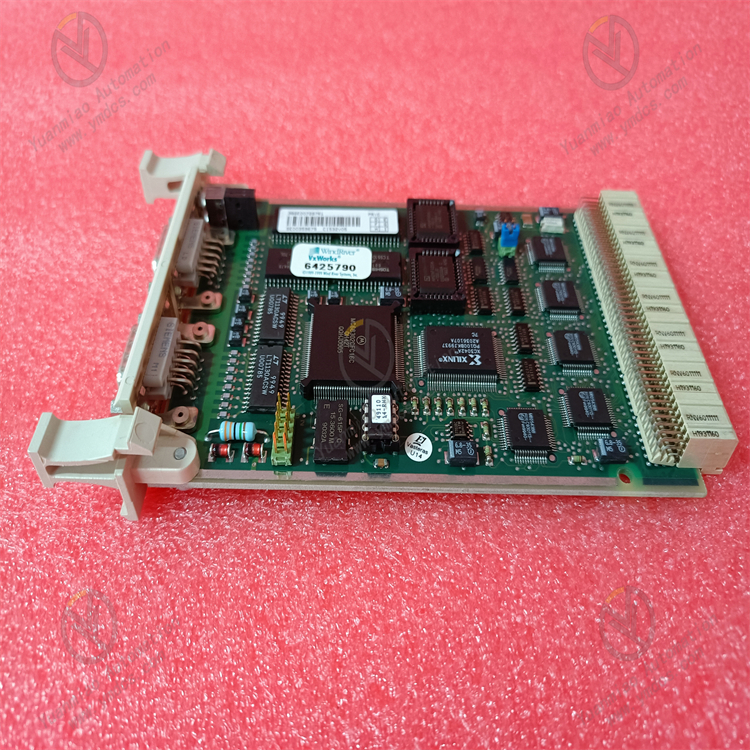
GE IS200VTCCH1CBB
1. Overview
The GE IS200VTCCH1CBB is a valve position control and feedback module developed for industrial gas turbine control systems. Its core positioning is a "precision position adjustment and status monitoring unit for critical gas turbine valves". It mainly serves industries such as power generation (e.g., F-class/H-class gas turbines in combined cycle power plants), petrochemicals (e.g., gas turbine-driven compressors in oil refineries), and energy (e.g., gas turbine waste heat power stations). As a key component of the GE Speedtronic Mark VIe gas turbine control system, it enables closed-loop control of "command issuance - position adjustment - status feedback" for core valves such as fuel valves, guide vane actuators, and bypass valves.
2. Technical Specifications
2.1 Core Valve Position Control Parameters
Control Channel Configuration
- Number of Channels: 4 independent valve position control channels. Each channel can be independently configured with control mode and actuator type, supporting "full activation of 4 channels" without performance degradation.
- Compatible Actuator Types:
- Electro-hydraulic proportional valves (input signal: 4-20mA DC, corresponding to 0%~100% opening);
- Electric actuators (input signal: 0-10V DC, corresponding to 0%~100% opening);
- Servo valves (input signal: ±5V DC, corresponding to -10%~110% opening, for high-precision adjustment).
- Control Modes: Supports three modes: "position closed-loop control", "speed control", and "torque control". The default mode is "position closed-loop control" (real-time output correction via feedback signals).
Position Feedback and Adjustment Performance
- Feedback Signal Types: Supports three position feedback methods: potentiometer (0-5V DC/0-10V DC), LVDT (Linear Variable Differential Transformer, ±5V DC), and encoder (incremental, 5000 lines/revolution).
- Feedback Precision: ±0.1% F.S. for potentiometer/LVDT feedback; ±0.05% F.S. for encoder feedback (corresponding to valve opening error ≤ 0.05%).
- Adjustment Response: Step response time ≤ 100ms (from 0% to 100% opening), overshoot ≤ 2%, steady-state error ≤ 0.1% (in position closed-loop mode).
- Output Driving Capacity: Each channel has a maximum output current of 2A (in 4-20mA mode) and a maximum output voltage of 10V (in 0-10V mode), which can directly drive small and medium-sized actuators (no external power amplifier required).
2.2 Physical and Environmental Parameters
Physical Specifications
- Dimensions: 220mm (length) × 160mm (width) × 80mm (height) (including mounting clips). Adopting the standard rack slot design of the GE Mark VIe system, it can be directly inserted into the I/O rack of the Mark VIe control cabinet. It is dimensionally compatible with modules of the same series (e.g., IS200SAMBH1ABA, IS200STAOH2AAA), allowing mixed installation in the cabinet to simplify layout.
- Weight: Approximately 1.3kg. The modular design supports insertion and removal by a single person, with a replacement time ≤ 5 minutes (equipped with quick-connect terminals).
- Terminals: Uses spring-loaded quick-connect terminals (compatible with 1.5mm²~2.5mm² wires). Terminals for valve position control output and feedback signals are independently partitioned to avoid signal interference, increasing wiring efficiency by 50%.
Environmental Adaptability
- Operating Temperature: -40℃~+70℃, meeting the operational requirements of high-temperature gas turbine rooms (up to 55℃ in poorly ventilated conditions in summer) and outdoor control cabinets in cold regions (-35℃ in winter). No preheating is required for low-temperature startup (-40℃), and the startup time is ≤ 20s.
- Humidity: 5%~95% (non-condensing, complying with IEC 60068-2-3 standard). In the high-humidity environment of coastal power plants, the circuit board shows no corrosion or leakage.
- Protection Rating: IP20 (for installation inside control cabinets), compatible with the overall IP54 protection system of the Mark VIe control cabinet, preventing dust from entering the module interior.
Vibration and Shock Resistance: Vibration resistance rating of 10g (10Hz~2000Hz, complying with IEC 60068-2-6), capable of withstanding continuous vibration during gas turbine operation (e.g., 10Hz vibration caused by rotor imbalance); shock resistance rating of 20g (11ms pulse, complying with IEC 60068-2-27), capable of withstanding shock loads during unit startup and shutdown.
- Electromagnetic Interference (EMI) Resistance: Complies with the EN 61000-6-2 industrial immunity standard. Electrostatic Discharge (ESD) protection: ±15kV (air discharge)/±8kV (contact discharge); radio frequency radiation immunity: 10V/m (80MHz~1GHz). In high-interference environments such as near generators and high-voltage cables, the valve position adjustment error is ≤ 0.2%.
2.3 Power Supply and Reliability Parameters
- Power Supply Requirements: Operating voltage: 24V DC (wide-range adaptation: 18V DC~36V DC), powered by the backplane of the Mark VIe system rack. Operating current ≤ 600mA (when 4 channels are fully activated), power consumption ≤ 14.4W, without increasing the power supply load of the cabinet.
- Isolation Performance: Three-level electrical isolation between control output, feedback input, and power supply, with an isolation voltage ≥ 2500Vrms for 1 minute. Common Mode Rejection Ratio (CMRR) ≥ 100dB (50Hz), Differential Mode Rejection Ratio (DMRR) ≥ 80dB, effectively blocking ground loop interference and signal crosstalk.
Reliability Indicators: Mean Time Between Failures (MTBF) ≥ 350,000 hours (per Telcordia SR-332 standard at 25℃), design life ≥ 20 years. Key components (e.g., driver chips, feedback acquisition chips) are selected from military-grade products, and the module supports "channel-level redundancy" (when a channel fails, backup channel parameter configuration can be activated).
- Communication Interface: Communicates with the Mark VIe controller (e.g., IC698CPE330) via the system backplane bus, with a data transmission rate of 100Mbps and latency ≤ 1ms. It supports channel parameter configuration, fault diagnosis, and valve position status reading through the GE ControlST configuration software.
3. Functional Features
3.1 High-Precision Valve Position Closed-Loop Control
- Adaptive PID Adjustment Algorithm: Built-in "adaptive PID" control algorithm that automatically optimizes PID parameters (proportional gain P, integral time I, derivative time D) based on valve type (e.g., fuel valve, guide vane valve). For example, for fuel valves (with large inertia and obvious lag), the algorithm automatically increases the integral time (I=2s) to reduce overshoot; for guide vane valves (with fast response and easy oscillation), it automatically decreases the proportional gain (P=2.5) to improve stability. The adjustment precision can reach ±0.1%, much higher than that of traditional fixed PID algorithms (±0.5%).
Multi-Feedback Method Integration: Supports three feedback methods (potentiometer, LVDT, encoder), and the adaptation scheme can be selected based on valve importance. For example, fuel valves (core adjustment components) use encoder feedback (±0.05% precision), while bypass valves (auxiliary adjustment) use potentiometer feedback (±0.1% precision), balancing control precision and cost. Meanwhile, the module is equipped with a "feedback signal fault tolerance" function. When the main feedback (e.g., encoder) fails, it automatically switches to the backup feedback (e.g., LVDT) to ensure uninterrupted control.
Nonlinear Compensation Function: Aiming at the nonlinear characteristics of valves such as "dead zone" and "hysteresis" (e.g., old fuel valves have a dead zone in the 10%~15% opening range), the module can use a "segmented linear compensation" algorithm to preset compensation coefficients for different opening ranges in the configuration software (e.g., for the 10%~15% opening range, the output signal is increased by an additional 0.5mA). This eliminates nonlinear errors, ensuring the deviation between the actual valve opening and the command is ≤ 0.1%.
3.2 Dedicated Adaptation for Gas Turbine Valve Control
- Optimization of Control Modes for All Operating Conditions: The module presets dedicated control parameters for the four core operating conditions of gas turbines: startup, loading, stable operation, and shutdown.
- Startup Condition (0~30% Load): Activates the "slow startup" mode, limiting the valve opening adjustment rate to 0.5%/s to avoid combustion chamber detonation caused by a sudden increase in fuel supply.
- Loading Condition (30%~100% Load): Activates the "fast response" mode, increasing the adjustment rate to 2%/s to meet the demand for rapid grid load growth.
- Stable Operation Condition (100% Load): Activates the "steady-state maintenance" mode, enhancing the PID integral effect to suppress opening drift caused by minor disturbances (e.g., grid voltage fluctuations).
- Shutdown Condition (100%~0% Load): Activates the "coasting control" mode, closing the valve slowly according to a preset curve (e.g., 5%/min) to match the unit's coasting process and avoid sudden speed drop.
Collaboration with Combustion Control Logic: Deeply collaborates with the combustion control logic of the Mark VIe controller, receiving "combustion stability signals" (e.g., combustion chamber pressure fluctuation value) in real time and dynamically adjusting the valve adjustment strategy. When combustion fluctuations are detected (pressure fluctuation ≥ ±0.05MPa), the module automatically reduces the valve adjustment rate (from 2%/s to 0.5%/s) and enhances the PID derivative effect to quickly suppress fluctuations, avoiding detonation or flameout (a single flameout can cause losses exceeding 500,000 yuan).
Safety Limit Protection: Each channel can be set with "mechanical limits" (e.g., maximum fuel valve opening of 95% to prevent overload) and "soft limits" (e.g., maximum opening of 30% during startup to prevent overheating), providing double protection for valve safety. When the valve approaches the limit (e.g., 90% opening), the module automatically reduces the adjustment rate to avoid valve jamming caused by hard impact (maintenance cost exceeds 100,000 yuan).
3.3 Industrial-Grade Reliability and Fault-Tolerant Design
- Extreme Environment Protection: The internal circuit board is coated with "nano-level three-proof paint + Teflon coating", providing triple protection against oil pollution, dust, and corrosion. In the high-oil-pollution environment of gas turbine rooms, the circuit board shows no oil accumulation or component corrosion after 5 years of continuous operation. The housing is made of magnesium-aluminum alloy (lightweight and with good thermal conductivity). When the module operating temperature reaches 70℃, the internal driver chip temperature remains ≤ 85℃ (lower than the rated temperature of 125℃), ensuring stable operation.
Channel-Level Fault Self-Diagnosis: Supports automatic diagnosis of 10 types of faults such as "output short circuit", "feedback disconnection", and "actuator overload". When a channel fails, the module immediately displays a fault code on the system HMI (e.g., "F07 = Channel 2 Feedback Disconnection") and records data such as valve position commands, actual opening, and feedback signals 10 seconds before the fault. This allows maintenance personnel to quickly locate the problem (reducing troubleshooting time from 2 hours to 30 minutes).
Redundancy Configuration Support: Supports "1:1 hot redundancy" configuration (main and standby modules operate in parallel). The main module synchronizes control parameters and valve position status to the standby module in real time. When the main module fails (e.g., power supply abnormality), the standby module automatically takes over the control of all channels within 10ms, with a valve position opening fluctuation ≤ 0.2%. It meets the IEC 61508 SIL 2 safety level requirements, making it suitable for critical scenarios such as gas turbines supporting nuclear power plants.
3.4 Convenient Operation & Maintenance and Intelligent Functions
- Visual Configuration and Debugging: Through the GE ControlST configuration software, parameters such as "valve type", "feedback method", "PID parameters", and "limit values" for each channel can be configured graphically. It supports the "parameter copy" function (copying fuel valve parameters to channels of the same type of valves), with the configuration time for 4 channels ≤ 10 minutes. Meanwhile, the software has a built-in "valve position simulation" function that can simulate valve response curves (e.g., step response, ramp response) under different commands, enabling debugging without on-site operation.
Remote Status Monitoring and Control: Remote operation and maintenance of the module can be realized through the Ethernet interface of the Mark VIe system. Maintenance personnel can view the "commanded opening", "actual opening", "adjustment deviation", and "fault status" of each valve in the central control room, and remotely modify PID parameters and limit values (e.g., adjusting the maximum opening of the fuel valve according to seasonal changes) without opening the cabinet on site, increasing maintenance efficiency by 60%.
Health Status Assessment: The module has a built-in "valve health assessment" function that automatically generates a "health score" (0~100 points) by analyzing historical adjustment data (e.g., adjustment frequency, overshoot, steady-state error). When the score is below 70 points (e.g., the adjustment frequency increases from 10 times per day to 50 times, indicating valve jamming), the module issues a "maintenance reminder" through the HMI, prompting early arrangement of valve maintenance to avoid unit shutdown caused by sudden faults.