Description
Part Number: IS220UCSAH1A
Manufacturer: General Electric
Series: Mark VIe
Product Type: PAMC Acoustic Monitor (Processor)
Software: ControlST V04.03.18C
Relative humidity: 5% to 95%, no-condensing
Power Requirements +32 V dc to 18 V dc
Microprocessor: Freescale Power PC (Power QUICC II PRO 667 MHz)
Memory: 256 MB DDR SDRAM
Operating System: QNX Neutrino
Weight: 2 lbs
Availability: In Stock
Country of Manufacturer: United States (USA)
FUNCTIONAL DESCRIPTION:
IS220UCSAH1A is an Embedded Controller Module manufactured and designed by General Electric as part of the Mark VIe Series used in GE Distributed Gas Turbine Control Systems. The UCSA controller is a product line of stand-alone computers that run the application code. The controller mounts in a panel and communicates with the I/O packs through onboard I/O network (IONet) interfaces. The I/O networks are private special-purpose Ethernet that supports only the I/O modules and the controllers. The controller operating system (OS) is QNX Neutrino, a real-time multitasking OS, designed for high speed, high reliability, and industrial applications. The UCSA controller platform is available for use in many applications, including balance of plant control and some retrofits. It does not have enough processing power, however for some advanced model-based control applications.

FEATURES:
Storage and Certification: The controller module is designed for use with the Mark VIe UCSA controller. It employs compact flash storage for its operational needs. It is important to note that this controller is not certified for IEC61508 safety loop usage, meaning it may not be suitable for applications with stringent safety requirements.
Power Requirements: The module requires a power supply in the range of 18 V DC to 32 V DC. This flexibility in power input, with a typical power consumption of 12.5 Watts, ensures compatibility with a variety of power sources, making it versatile and adaptable.
Temperature Tolerance: The controller exhibits robust temperature tolerance, allowing it to operate effectively in a wide range of environmental conditions. It can function reliably in temperatures ranging from 0 to 65 degrees Celsius. Moreover, it is designed without the need for a fan for cooling, simplifying its installation and maintenance while maintaining a cool operational profile.
Hazardous Environments: The controller module is suitable for use in hazardous environments and is compatible with NFPA Class 1, Div. 2 applications. This means it can be employed safely in areas where potentially explosive substances are present, further extending its range of possible use cases.
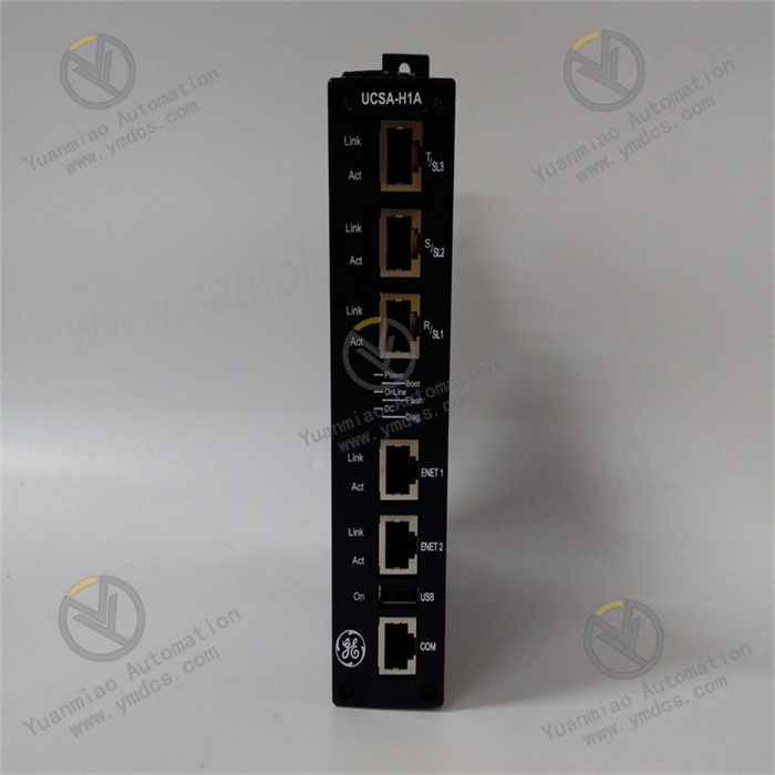
Front Faceplate Connectivity: The front faceplate of the controller module features a set of user-friendly connectivity options. It includes six female jack connectors, allowing for easy and secure cable connections. Additionally, a USB port is provided for convenient data exchange and configuration. The faceplate also incorporates a series of LED indicators that provide valuable information about the module's status and operation.
LED Indications: The LED indicators on the front panel offer essential insights into the controller's status. The Link/Act LED indicators on the left side of the faceplate provide real-time feedback on network connectivity. In the center of the faceplate, a line of LED indicators is labeled Power, Boot, Online, Flash, DC (indicating power source status), and Diag (diagnostic status). These LEDs make it easy to monitor the controller's operational health and detect any issues.
Ethernet Connectivity: Supports Ethernet connections through jack connectors. This feature allows seamless integration with other control systems, such as Mark VI, Mark VIe, or EX2100 excitation controls. It also facilitates communication with maintenance and operator stations, enabling remote monitoring and control capabilities.

General Operation Guide for GE IS220UCSAH1A
Select a well-ventilated location with a temperature range of 0 to 65 degrees Celsius and no strong electromagnetic interference. Ensure sufficient space around the installation site for subsequent maintenance and heat dissipation.
Install the controller module in a suitable cabinet and fix it according to the instructions. For multi-module systems, pay attention to the spacing and installation order between modules; the main controller is typically installed in the first slot on the left (Slot 1).
Connect an 18-36V DC power supply according to the module’s power requirements, ensuring stable and reliable power supply. Pay attention to the correct connection of positive and negative poles.
Connect required peripheral devices (e.g., keyboards, monitors, sensors, actuators) to the corresponding interfaces on the front panel. Each connector is clearly labeled on the front panel; refer to the detailed lead-out wire instructions in the appendix for connection.
Connect the module to other devices or systems via Ethernet, serial ports, CAN ports, or fiber optic interfaces according to actual application needs to achieve data transmission and communication. For example:
- Connect to a host computer or HMI system via Ethernet;
- Connect to other controllers or intelligent devices via CAN bus.
Before powering on, check that all connections are secure and the module’s jumper settings are correct to ensure no loose connections or short circuits.
Power on the system. The screen will display multiple messages, including the names, versions, and copyright dates of various BIOS modules. Wait for the system to complete self-check and startup.
For precise time synchronization, use the system NTP server or related tool software (e.g., toolboxst application) to set the initial time and date. The module’s real-time clock is powered by a CMOS battery, which may require re-setting the time after installing or replacing the battery.
If an external drive module is installed, run the BIOS setup program to configure the drive type. Refer to the relevant appendix or instructions for specific setup methods.
If the module requires an operating system, install it according to the manufacturer’s instructions. The QNX Neutrino operating system is typically pre-installed and basically configured at the factory but may require parameter adjustments and software installations for specific applications.
Configure the module’s network parameters (e.g., IP address, subnet mask, gateway) according to the network topology and communication requirements. If redundant networks are supported, set corresponding redundant parameters to ensure network reliability and stability.
Use GE’s dedicated programming software or third-party programming tools supported by the module. These software typically feature graphical programming interfaces to facilitate logic design and function configuration.
Create a new project in the programming software and specify information such as the project name and target device (i.e., IS220UCSAH1A module).
Write control logic programs using programming languages (e.g., ladder diagram, C language, structured text) according to specific application needs. For example:
- Set pulse generation parameters;
- Define the processing method for input and output signals;
- Write alarm logic.
Configure parameters for input and output channels (e.g., signal type, range, filtering parameters) according to the types of connected sensors and actuators. Ensure that input channels accurately collect external signals, and output channels control external devices as required.
If the module needs to communicate with other devices, configure parameters such as communication protocols, addresses, and baud rates to ensure normal data transmission with other devices.
Download the written program to the IS220UCSAH1A module. Ensure a stable connection between the module and the programming software during the download process to avoid interruptions or errors.
After the program is downloaded, start the module’s operation via the programming software or HMI interface. The module will execute tasks according to the written control logic, collect input signals, process data, and output control signals to external devices.
Monitor the module’s operating status in real time through the HMI interface, the programming software’s monitoring function, or other monitoring tools, including input/output signal values, variable changes, device operating status, etc. Timely identify issues and make adjustments.
The module has fault detection and alarm functions. If anomalies are detected, alarm information will be displayed via LED indicators, alarm signals, or the monitoring interface. According to the alarm prompts, promptly troubleshoot the cause and take corresponding actions, such as checking device connections, reviewing program logic, or replacing faulty components.
Regularly maintain the module, inspect hardware status, and clean dust to ensure good heat dissipation. If new software versions or function updates are available, upgrade the software according to GE’s recommendations and instructions to achieve better performance and functions.
Always refer to the detailed user manual and technical documentation for operation to ensure correct and safe use. If problems arise, contact GE technical support or professional engineers for assistance
![]()