Description
1. Product Overview
Model: IS400TDBTH6AEF
Brand: GE General Electric
Product Name: Discrete Single-Ended I/O Terminal Board for Mark VI Turbine Control System
Product Positioning: A dedicated supporting board for GE Speedtronic Mark VI core turbine control system. It serves as front-end signal conversion and acquisition hardware for gas turbine and steam turbine control systems. It provides standardized field signal access, electrical isolation and terminal expansion for main control modules, acting as a critical hub in the signal link of unit control systems.
Core Functions: Implement terminal transition, wiring matching, signal filtering and electrical isolation for various field discrete input and output signals. Enable reliable data communication between local field devices, main control CPU and I/O boards. Ensure stable and error-free transmission of signals for turbine start/stop control, status acquisition, interlock protection and alarm output, preventing signal distortion and false operation caused by field interference.
Applicable System: Complete GE Speedtronic Mark VI control system for gas turbines and steam turbines. Compatible with IS400 series main control and I/O modules, and supports linkage architecture of DCS and PLC for large power units.
Application Scenarios: Widely deployed in thermal power plants, combined cycle power stations, petrochemical captive power plants, metallurgical turbine units and other key industrial sites. Designed for installation in turbine control cabinets and main system cabinets, serving as a core spare part for automatic control systems of large power equipment.
2. Technical Features
Dedicated Compatibility with Original System Custom-developed for GE Mark VI turbine control system. Hardware pins, communication protocols and signal logic fully match the original system without compatibility deviation. Not interchangeable with other brands or legacy GE control systems, meeting strict long-term stable operation standards of power units.
Industrial-Grade Signal Isolation Protection Onboard dedicated signal filtering circuits, optoelectronic isolators and surge suppression components. Effectively suppress electromagnetic interference generated by inverters, contactors and high-power equipment inside cabinets, attenuate line clutter and transient pulses, and guarantee accurate, drift-free discrete signal transmission without false triggering.
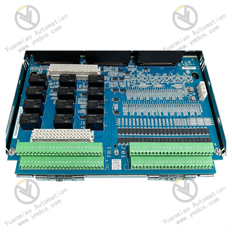
Standardized Terminal Expansion Design Equipped with high-density screw terminals with neat layout to support centralized connection of multiple discrete signals. Simplifies field wiring, reduces crosstalk risk, and facilitates wiring verification, maintenance and troubleshooting.
Highly Reliable Industrial Hardware Architecture Adopts military-grade PCB materials and surface-mount devices with excellent shock resistance, dust resistance, temperature variation tolerance and anti-aging performance. Supports 7×24-hour continuous operation in power plants and adapts to harsh cabinet environments featuring high temperature, high humidity and strong interference.
Precise Signal Matching & Transmission Strictly complies with Mark VI system signal sampling timing and voltage level standards. Accurately transmits critical signals including unit interlock protection, start/stop commands, equipment status feedback and fault alarms, avoiding signal delay, loss and distortion to ensure reliable execution of unit protection logic.
Modular Structure for Easy Maintenance Standard rack plug-in design for convenient insertion and secure fixation. Supports independent disassembly and replacement without modifying system wiring or configuration, greatly cutting maintenance cost and downtime during overhaul and spare part replacement.
- Built-in Hardware Self-Test Mechanism Integrated hardware monitoring circuits continuously detect terminal circuit continuity, abnormal signals and onboard power supply faults. Cooperates with the main control system to trigger alarms, helping maintenance staff quickly locate wiring and board faults.
3. Specification Parameters
| Item | Parameter |
|---|---|
| Model | IS400TDBTH6AEF |
| Device Type | Discrete Single-Ended I/O Terminal Board for Turbine Control System |
| Applicable System | GE Speedtronic Mark VI Turbine Control System |
| Signal Type | Discrete Digital Input/Output Signals, Unit Interlock Status Signals, Alarm Signals |
| Connection Mode | Rack plug-in installation, screw terminal wiring, onboard ribbon cable interfacing with main control board |
| Operating Power Supply | Internal regulated system power supply (original standard matching) |
| Operating Temperature | 0℃~65℃ (rated cabinet condition) |
| Storage Temperature | -20℃~85℃ |
| Ambient Humidity | 5%~95%, non-condensing |
| Protection Design | Optoelectronic Isolation, Surge Suppression, EMC Protection, Signal Filtering |
| Applicable Equipment | Control Systems for Gas Turbines, Steam Turbines and Combined Cycle Power Units |
| Origin | Original Imported from USA |
| Characteristics | System-specific, non-interchangeable, high temperature resistance, anti-interference, long service life |
4. Working Principle
Signal Access and Preprocessing After power-on initialization, the board continuously receives discrete digital signals from field sensors, actuators, local switches and interlock devices. All external signals undergo noise reduction, voltage regulation and isolation preprocessing via onboard filtering, current limiting and optoelectronic circuits to eliminate industrial clutter and interference pulses, converting non-standard field signals into standard logic levels recognizable by the control system
Signal Transmission and Logic Matching Processed standard signals are transmitted steadily through onboard high-speed ribbon cables to Mark VI main control boards and CPU modules, providing raw data including unit equipment status, operation feedback, fault alarms and interlock triggers. Meanwhile, it receives start/stop, reset and interlock action commands issued by the main controller for reverse signal transmission, realizing bidirectional data exchange between the system and field devices.
Circuit Isolation and Fault Protection The onboard isolation architecture establishes electrical separation between primary field equipment and secondary control loops. It prevents impact on the main control system caused by field short circuits, voltage surges and leakage, protecting core CPU and control boards and improving fault resistance and operational safety of the whole control system.
Real-Time Status Monitoring and Feedback Onboard hardware circuits continuously monitor circuit continuity, signal status and power supply anomalies of each terminal channel. Once open circuits, abnormal signals or channel failures are detected, fault feedback signals are uploaded to the system to trigger corresponding alarms and support fault recording, logic locking and safety protection actions.
- Support for System Interlock Logic Stably transmits critical unit interlock protection signals throughout operation, precisely matching core control logic including turbine start-stop sequence, fault trip and safety interlock. Ensures closed-loop execution of logic under normal startup/shutdown, steady-state operation and emergency shutdown conditions, serving as front-end hardware guarantee for safe and stable unit operation.
5. Common Faults and Troubleshooting
Phenomenon: No response after power-on; all corresponding channels have no signals Possible Causes
① Poor contact between board and backplane slot, oxidized and dusty gold fingers;
② Damaged internal power circuit or blown fuse on the board;
③ Abnormal backplane power supply or faulty slot.
Troubleshooting Cut off system power and fully discharge; extract the board, clean gold fingers and slot dust, then reinsert firmly. Verify backplane slot supply voltage; check onboard fuses — never short blown fuses. If no response occurs with normal power and slot condition, the board suffers hardware damage and needs replacement.
Phenomenon: Abnormal signal transmission, frequent false status alarms and signal jitter Possible Causes
① Loose field wiring, poor terminal contact, inadequate shielding earthing;
② Aging and failure of onboard signal filtering and isolation components;
③ Severe on-site electromagnetic interference triggering signal fluctuation.
Troubleshooting Tighten terminals one by one, inspect wiring damage and loose connections, and standardize shield earthing. Identify interference sources from high-power field equipment and strengthen cable isolation. If signal jitter persists with correct wiring and environment, the signal conditioning circuit is faulty and board replacement is required.
Phenomenon: Partial channel failure; single-channel signals cannot be acquired or output Possible Causes
① Oxidation, ablation and poor contact of single-channel terminals;
② Damaged single-channel signal chips or isolation devices on the board;
③ Burnt single-channel circuit caused by external wiring short circuit.
Troubleshooting Power off and inspect fault channel terminals; clean oxidized terminals and repair ablated wiring. Check and rectify short circuit or leakage faults in external cables. If channels remain invalid after eliminating external faults, local hardware damage exists and the whole board must be replaced.
Phenomenon: Abnormal unit interlock signals; false or missed triggering of protection logic Possible Causes
① Signal transmission delay and accuracy drift on the board;
② Signal level offset due to aging isolation circuits;
③ Poor contact of ribbon cable between board and main control board leading to data packet loss.
Troubleshooting Replug and fasten the connecting ribbon cable between the board and main control board, clean connectors. Verify system signal threshold parameters and calibrate signal precision. Inspect aging isolation and filter components. Replace the board directly if repair is unavailable to avoid unit shutdown accidents caused by interlock failure.
Phenomenon: Excessively high operating temperature of the board and local overheating inside cabinet Possible Causes
① Poor cabinet heat dissipation, blocked air ducts and heavy dust accumulation;
② Component aging and abnormal power consumption after long-term operation;
③ Heat accumulation under simultaneous high-load operation of multiple channels.
Troubleshooting Clean dust in cabinet air ducts and cooling holes to improve ventilation and maintain ambient temperature within rated range. Continuously monitor board temperature. If overheating remains despite proper heat dissipation, component aging is confirmed; replace spare parts in advance to prevent faults.
Phenomenon: System fails to recognize the board; no hardware identification information displayed Possible Causes
① Abnormal board firmware or program loss;
② Faulty backplane communication slot or ribbon cable communication failure;
③ Damaged hardware identification circuit on the board.
Troubleshooting Reinsert the board and communication ribbon cables, restart the system for re-identification. Check firmware version compatibility with the system. If recognition fails after re-flashing compatible firmware, hardware fault is confirmed and genuine original board replacement is required.