Description
I、Product Overview
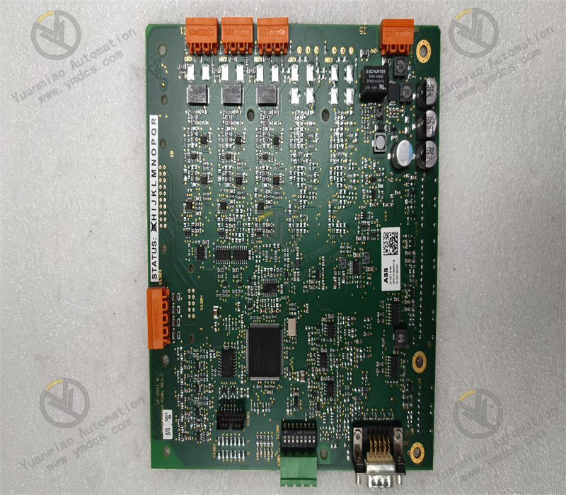
Model: 80190‑440‑03‑R
Brand: Allen‑Bradley (Rockwell Automation)
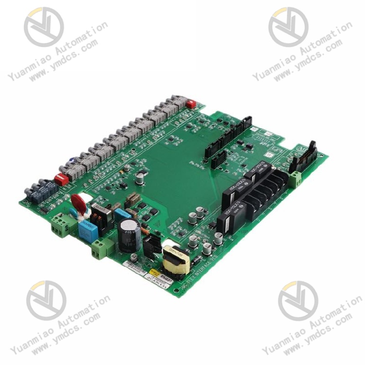
Name: Dedicated Interface Control PCB Board for SMC Flex Soft Starter
Positioning: Core internal signal communication and control interface board of SMC Flex soft starter, serving as the main control unit of the soft starter.
Function: Acts as a signal bridge between the soft starter power unit, operator panel and external control system; collects motor current, temperature and status signals, executes soft start/soft stop logic and protection algorithms, and supports panel commissioning and bus communication. Compatible Equipment: Allen‑Bradley SMC Flex Series Intelligent Motor Soft Starters
Application Scenarios: Soft start control systems for three‑phase asynchronous motors such as fans, water pumps, compressors and belt conveyors; widely deployed in complete electric control cabinets for power plants, water treatment, metallurgy and chemical industries.
II、Technical Features
- Dedicated Integrated Hardware Developed exclusively for the SMC Flex soft starter platform. It integrates signal conditioning, I/O driving, communication transceiving and fault detection circuits, and cannot be used universally for other variable frequency drives or soft starter models.
- Multi‑Type Signal Processing Supports analog current sampling, NTC temperature signals, digital discrete input / relay output; isolates and suppresses noise for feedback signals from the power circuit.
- Human‑Machine Interface Connects to the dedicated SMC Flex operator keypad panel, enabling parameter read/write, operating status display and fault code retrieval.
- Industrial‑Grade Anti‑Interference Design The PCB is equipped with power supply filtering, optocoupler isolation and surge suppression components to withstand electromagnetic interference generated by variable frequency drives and contactors inside control cabinets.
- Hardware Channels for Built‑in Motor Protection Logic Cooperates with firmware to collect trigger signals for protections including overload, phase loss, phase unbalance, start timeout and thyristor overheating.
- Bus Expansion Support Reserved slots accommodate communication options such as DeviceNet to realize networked remote monitoring with Logix‑series PLCs.
- Version Suffix “‑R”: Upgraded revised version. It addresses defects in communication stability and sampling accuracy found on the early base version 80190‑440‑03.
III、Specification Parameters
| Item | Parameter |
|---|---|
| Power Supply | Supplied by the internal control power supply of SMC Flex soft starter (typical internal 24VDC supply) |
| Signal Types | Analog current sampling signal, NTC temperature signal, digital DI/DO, panel serial communication |
| Onboard Interfaces | Ribbon cable connector (to power mainboard), operator panel port, external control terminal block, communication expansion slot |
| Operating Temperature | 0~60℃ (cabinet mounting); Storage: ‑20~70℃ |
| Ambient Humidity | 5%~95%, non‑condensing |
| Vibration Resistance | 5~500Hz, 1g (fixed cabinet installation) |
| Protection Class | Bare PCB; must be installed inside soft starter enclosure (IP00) |
| Origin | Original Made in USA |
| Compatible Series | Matching mainboard for SMC Flex 150 Series Soft Starters |
| Compatible Model Reference | Replaces earlier version: 80190‑440‑03 (legacy version without ‑R suffix) |
IV、Working Principle
- Signal Acquisition Phase Continuously receives three‑phase current sampling signals, thyristor heatsink temperature signals, and external start/stop, emergency stop discrete signals transmitted from the soft starter power board. Signals are conditioned via operational amplifier circuits and isolated by optocouplers and converted into recognizable voltage levels for the microcontroller.
- Logic Operation and Control Output The onboard MCU executes soft starter control algorithms: ramp voltage start, current‑limit start and soft stop. Sampled values are compared against protection thresholds in real time. Once thresholds are exceeded, a blocking signal is sent immediately to turn off thyristors.
- Human‑Machine Communication Bidirectional communication with the operator panel via dedicated serial port: transmits operating parameters downward, uploads current, voltage and fault codes upward; receives modified parameters including start time, initial voltage and protection thresholds from the panel.
- Interaction with External Systems Digital output terminals relay signals such as running status, fault alarm and bypass ready. When communication modules are fitted, motor operating data is uploaded to the PLC control system.
- Fault Latching Mechanism Upon protective trip, the board latches fault codes and maintains fault output. Latching can only be cleared via power cycle reset or panel reset.
V、Common Faults and Troubleshooting
- Phenomenon: No display on operator panel after power‑on; soft starter completely inoperable Possible Causes ① Loose ribbon cable between the board and power mainboard, oxidized pin contacts; ② Damaged auxiliary power supply chips on the board; ③ Blown fuse in input power circuit. Troubleshooting Cut off power and allow sufficient discharge; reinsert ribbon cables and clean gold fingers; measure input power supply to the board. Never short the blown fuse directly. Check for short circuit risks on the power board and replace the interface board if necessary.
Phenomenon: Panel lights up, but frequent false alarms for phase loss / current unbalance Possible Causes ① Aging components within the current sampling circuit; ② Poor ribbon cable contact leading to attenuated sampling signals; ③ Faulty operational amplifiers in the board’s signal conditioning circuit. Troubleshooting Secure internal ribbon cables; verify three‑phase load balance of the motor. If loads remain balanced while alarms persist, hardware failure of the interface board is confirmed.
- Phenomenon: Frequent overheating protection during soft start (heatsink temperature reading normal) Possible Causes Damaged resistors or capacitors within the board’s NTC temperature measurement circuit, resulting in temperature sampling drift. Troubleshooting Measure resistance values of external temperature sensors. Replace the 80190‑440‑03‑R board if sensors are intact.
- Phenomenon: Parameters cannot be saved and lost after power cycle Possible Causes Faulty onboard non‑volatile memory chip. Troubleshooting Try factory reset and re‑download parameters. Replace the mainboard if the fault remains.
- Phenomenon: Communication failure; PLC fails to read data from soft starter Possible Causes Damaged communication circuit, poor contact of expansion slot; mismatched firmware version. Troubleshooting Reinsert communication module; verify firmware revision of the interface board; inspect communication wiring, shielding and earthing.