Description
ABB REF615C_C HCFCACABANB2AAN1XC
I. Basic Information
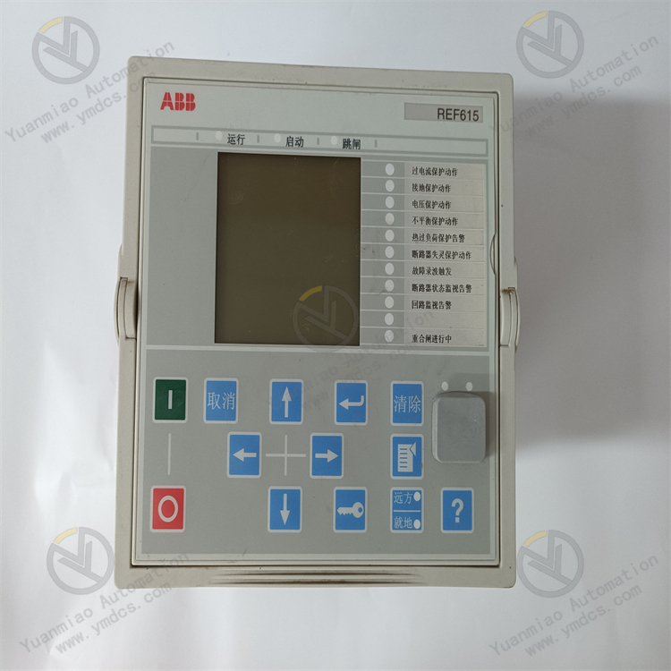
Model: REF615C_C | Order Code: HCFCACABANB2AAN1XCProduct Definition: ABB Relion®615 series Medium-Voltage Feeder Intelligent Electronic Device (IED). Configured per IEC Type C specification (Non-directional Overcurrent + Non-directional Earth Fault Protection). This all-in-one integrated relay integrates protection, measurement & control, energy metering, fault recording and communication functions. It is designed for 10kV~35kV distribution feeders, auxiliary power outgoing circuits and new energy grid-connection points, serving as a core replacement spare part for technical retrofits of existing power distribution systems in utility substations, petrochemical and metallurgical captive power plants.
Brand: ABB | Origin: Finland
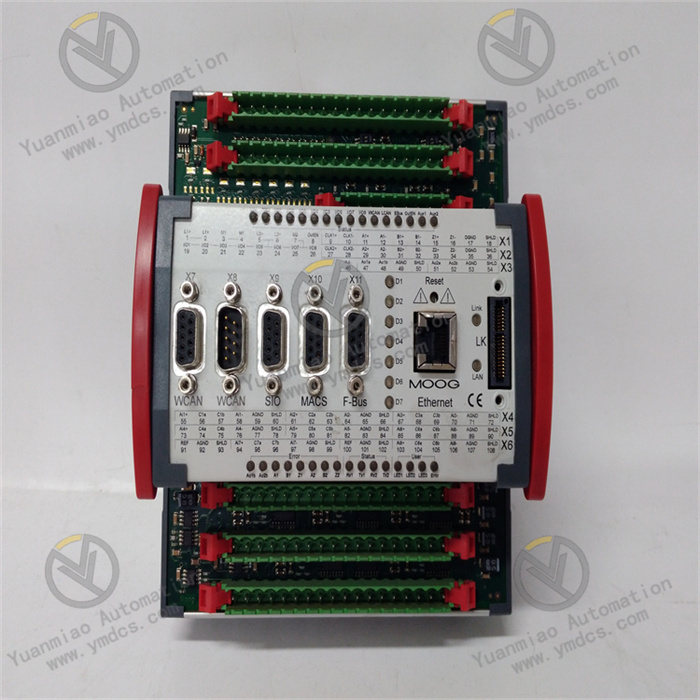
Product Type: 4U drawer-type pluggable protection relay (modular front-display & rear-wiring structure, enabling unit replacement without system shutdown).Compatibility: 10/20/35kV cable / overhead feeders, ring main units, package transformers, PV/wind farm grid tie-in points and industrial auxiliary power distribution systems; compatible with ABB SCADA and 800xA DCS power subsystem interface.
Mounting: Flush cutout installation on switchgear panel; Overall dimension: 177(H)×179.8(W)×201(D) mm, Net weight ≈3.9kg. Front panel IP54 ingress protection, rear terminal compartment IP20. PCB coated with Grade G3 anti-corrosion conformal coating complying with ISA71.04 standard to adapt to dusty and humid environments in chemical plants and power stations.
Standard Configuration: Large-size Chinese-language LCD + membrane function keys, local status alarm LEDs, rear terminal block (CT/PT analog terminals, digital input/output terminals), dual onboard Ethernet + RS485 communication ports and front-side USB service port.
Order Code Breakdown: HCFCACABANB2AAN1XC
H = Complete unit with enclosure;C = IEC international standard compliance;F = Feeder protection dedicated model;C = Type C function configuration (Non-directional OC + Non-directional Earth Fault);A = Standard base I/O configuration;B = No RTD temperature measurement;A = No arc flash protection;N = No optional plug-in modules;B2 = Dual Ethernet communication ports;A = No extra optional hardware;A = Standard DI/DO allocation;N = No additional optional accessories;1 = Wide-range power supply: 48~250VDC / 100~240VAC;XC = Hardware revision + spare reserved code.
II. Technical Specifications
(1) Analog Sampling & Power Supply Parameters
Analog Input: Rated CT 1A/5A, PT 100V; Current & voltage measurement accuracy Class 0.2, active/reactive energy metering accuracy Class 0.5S; Standard configuration: 4 current inputs + 3 voltage inputs.
Power Supply: Wide-range adaptive 48~250VDC / 100~240VAC, total power consumption ≤18W; built-in surge, reverse polarity and EMC hardware protection on power terminal.
Digital Circuits: 16 passive digital inputs (DI), 12 relay trip digital outputs (DO) with online trip circuit breakage monitoring; Single contact rating: AC250V/5A, DC220V/3A.
(2) Communication Specifications
- Dual independent RJ45 Ethernet ports: IEC61850 MMS + GOOSE (PRP redundant networking);
- 1 isolated RS485 port: Modbus RTU, IEC60870-5-103;
Front USB port: Local parameter downloading, firmware upgrade, fault record export;
All communication ports equipped with ≥2500VAC optoelectronic isolation to eliminate ground loop interference.
(3) Environmental Specifications
Continuous operating temperature: -25℃ ~ +55℃; Storage temperature: -40℃ ~ +70℃;Ambient humidity: 5%~95% RH non-condensing; Fully compliant with IEC60255 and Level 4 IEC61000 EMC industrial immunity standards against severe substation electromagnetic interference.
III. Core Features
1. Comprehensive Relay Protection (Core of Type C Configuration)
- Three-stage non-directional overcurrent protection (Instantaneous / Definite Time Instantaneous / Overload) + inverse-time overcurrent protection;
- Three-stage non-directional earth fault protection (optimized for resistance-grounded or solidly-neutral-grounded distribution networks);
- Thermal overload, PT fuse failure, CT open-circuit, circuit breaker failure, three-phase unbalance, under/overvoltage & underfrequency protection; User-defined programmable interlock logic configurable via PCM600 software.
2. Full-Scale Measurement & Energy Data Acquisition
Real-time sampling of three-phase current, voltage, active/reactive power, power factor, frequency and forward/reactive active & reactive energy; data readable locally via LCD and remotely uploaded to SCADA system; built-in daily & monthly energy freeze statistics function.
3. Fault Waveform Recording & Complete Event Logging
- Fault Recorder: Captures full waveform of 8 cycles pre and post fault, exportable in standard COMTRADE format;
- Event Logger: Stores ≥1000 millisecond time-stamped events (protection operations, status changes, alarms, parameter modifications); data permanently retained after power loss.
4. Dual-Redundant IEC61850 Communication
Dual Ethernet with PRP redundant architecture; seamless automatic switchover upon single port failure; GOOSE messaging enables inter-panel interlocking tripping complying with smart substation networking codes.
5. Full Hardware Self-Diagnosis & Local Alarm
Full startup self-test covering power supply, sampling circuits, trip output loops and communication chips; zone-divided front-panel LED indicators for fault, protection trip and communication failure; abnormal alarms automatically uploaded to master station; multi-level password access control to prevent unauthorized parameter modification.
6. Hot-Swap Maintenance Without Substation Shutdown
Drawer pull-out main unit with fixed rear terminal base; faulty unit replacement requires no field rewiring and can be implemented with switchgear live.
IV. Operating Principle
Power-on → Full power & hardware self-check → Load preset protection settings → Real-time primary electrical quantity acquisition via CT/PT;
Fault Trip Downlink: Line fault → Measured value exceeds threshold → Protection logic activation → DO relay drives circuit breaker opening, meanwhile fault timestamp and fault magnitudes are logged;
Data Uplink: Real-time analog & status data transmitted to substation master station / 800xA DCS via dual Ethernet or RS485;
Link Abnormality: Automatic switchover to standby Ethernet channel when one communication port fails, local alarm LED lit with corresponding status alarm reported to upper monitoring system.
V. Application Scenarios
- Feeder protection for outgoing bays of 10kV/35kV municipal urban distribution substations;
- Retrofit of 10kV auxiliary feeder protection for thermal power, petrochemical and coal chemical captive power plants;
- Measurement & protection for 35kV grid tie points and package transformer feeders of PV & wind power stations;
- Replacement spare relays for distribution ring network renovation inside metallurgy and cement heavy industrial facilities.