Description
1. Overview
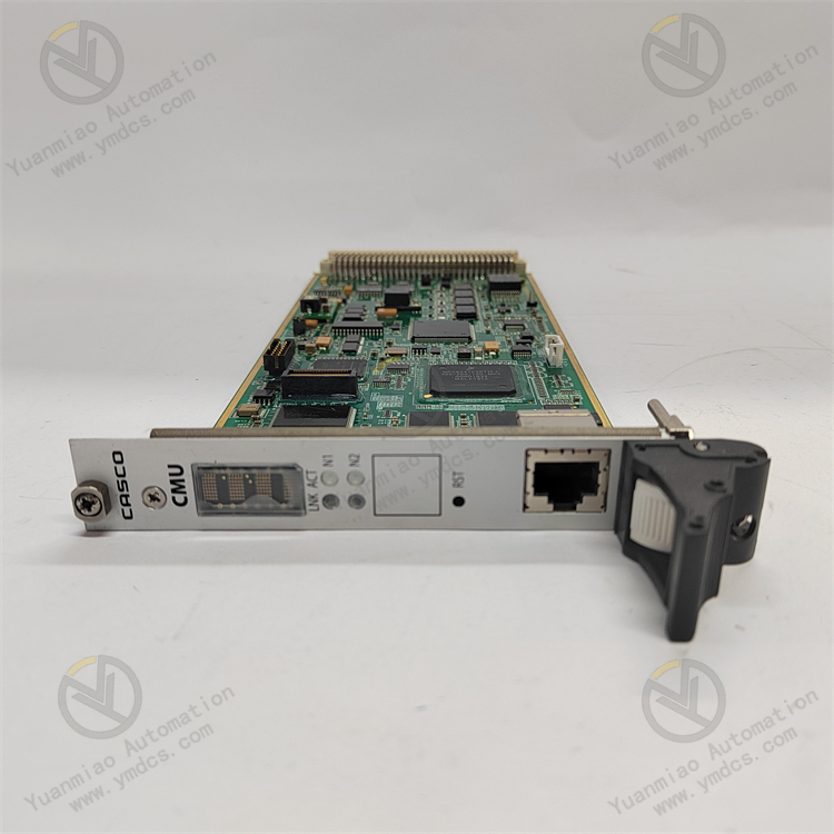
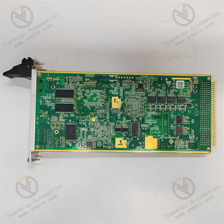
ALSTOM CMU 42015-115-00 is an industrial dedicated CMU (Control Monitoring Unit) . Serving as a core functional module for power and industrial control systems, it is developed for large-scale power equipment, industrial automation measurement & control systems and energy power units. It integrates all-in-one functions including signal acquisition, data computation, logic control, equipment monitoring, communication transmission and power supply voltage regulation. Adopting an industrial compact modular design, this hardware features outstanding stability, high-precision signal processing and wide communication compatibility. Suitable for harsh industrial scenarios such as power stations, industrial energy facilities and automated production lines, it is mainly applied to on-site process signal collection, equipment operation status monitoring, system logic scheduling, data exchange transmission and regulated power supply control. It acts as a key matching unit for ALSTOM complete industrial control and power control systems.
2. Technical Features
2.1 High-Precision Signal Processing Ensures Accurate and Reliable Condition Monitoring
2.2 All-In-One Integrated Design Delivers High Functional Integration
2.3 Abundant Hardware Interfaces Enable Excellent On-Site Adaptability
2.4 Multi-Protocol Industrial Communication Enhances System Integration
2.5 Wide-Range Power Adaptability Ensures Reliable Power Supply
2.6 Industrial-Grade Protection Design Accommodates Harsh Environments
3. Specification Parameters
3.1 Basic Parameters
- Model: CMU 42015-115-00
- Product Series: ALSTOM CMU Control Monitoring Unit Series
- Manufacturer: ALSTOM
- Device Type: All-in-one industrial control & monitoring functional module (CMU)
- Compatible Systems: ALSTOM original complete power control systems, industrial automation DCS/PLC systems, energy power measurement & control systems
- Application Scenarios: Power plant equipment measurement & control, industrial energy facility monitoring, automated production line condition control, technical upgrade of legacy control systems
- Core Functions: High-precision signal acquisition & processing, equipment status monitoring, logic control scheduling, regulated power supply control, multi-protocol data communication, fault self-diagnosis & alarming, data storage & uploading
- Operating Modes: 24-hour continuous unattended operation, real-time signal acquisition & calculation, dynamic condition regulation, fault-tolerant operation, remote online monitoring
- Compatibility: Matches original system protocols and hardware architecture; supports non-destructive in-situ replacement of legacy same-series modules and mainstream industrial control systems
3.2 Power & Electrical Parameters
- Input Power: Wide-range AC 165V~275V / 220VDC
- Rated Output Voltage: 115V
- Output Frequency: 50Hz±0.5Hz
- Rated Output Current: 2.3A
- Compatible Battery Voltage: 24VDC
- Max Charging Current: ≤5A
- Charging Cutoff Voltage: 27.4V±0.4VNote: The figure "42015W" in the original text is the model number fragment rather than actual power rating, and thus excluded from power parameters
- Energy Efficiency: ≥98.5% under rated load
- Electrical Protection: Multi-layer hardware defense against overvoltage, overcurrent, short circuit, surge, reverse polarity and overcharge; voltage regulation tolerance and power outage backup available
- Insulation: Galvanic isolation between power, signal and communication circuits to eliminate leakage and signal crosstalk
3.3 Signal Interface Parameters
- Digital Input (DI): 8 channels, DC24V rated input, 5mA per channel; compatible with dry and wet contact signals
- Digital Output (DO): 6 relay contact outputs, contact rating AC250V/3A, DC30V/2A for direct driving of field contactors and alarm devices
- Analog Processing Precision: Accurate collection and parsing of millivolt/milliampere weak signals with excellent filtering noise reduction and calibration performance
- Signal Performance: Fast response, strong anti-interference and zero drift for signal acquisition under complex industrial conditions
3.4 Communication Parameters
- Communication Interfaces: Dual RS485 ports, industrial Ethernet, CAN bus
- Supported Protocols: Modbus RTU, Profibus and other mainstream industrial protocols
- Communication Performance: Stable low-latency lossless transmission supporting real-time data exchange, remote configuration and fault log upload
- System Integration: Seamless connection to DCS, PLC, configuration software and remote O&M platforms for centralized management and data archiving
3.5 Environmental Parameters
- Operating Temperature: -40℃ ~ +70℃ wide industrial temperature range accommodating enclosed cabinet heat and temperature swings
- Storage Temperature: -30℃ ~ +80℃ for long-distance transit and offline storage
- Operating Humidity: 5%–95% RH (non-condensing); resistant to condensation-induced short circuits for humid workshops and power stations
- EMC Compliance: Meets high-level industrial EMC standards against harmonics, RF radiation, power fluctuation and pulse disturbance
- Mechanical Performance: Tolerates standard industrial vibration and shock; seismic, dust-proof and anti-aging for permanent cabinet mounting
3.6 Structural & Mechanical Parameters
- Overall Dimensions: 167mm × 148mm × 55mm (compact modular design)
- Total Weight: Approx. 10kg
- Mounting: Standard DIN rail or embedded cabinet installation for easy assembly and secure fastening
- Structural Features: Enclosed dustproof and moisture-proof layout with neat arrangement and uniform heat dissipation suited to compact cabinet layout
4. Working Principle
After power-up, ALSTOM CMU 42015-115-00 automatically completes hardware self-test, power loop verification, interface initialization, communication link matching and system parameter loading. Once all diagnostics pass, it enters regular operation as the core signal processing and condition regulation hub of the whole control system.
During runtime, multi-channel digital and analog input ports collect field equipment status signals, process parameters and condition feedback in real time. After high-precision filtering, noise reduction and calibration calculation, data is parsed and operating conditions are judged. Built-in control programs output regulating commands dynamically based on preset process logic and control parameters. Relay output ports drive field contactors, alarms and actuators to realize equipment start/stop management, closed-loop process regulation and abnormal alarming.
Voltage regulation and charge protection run continuously in the power circuit. Automatic voltage correction, regulated output and battery charging compensate for on-site voltage fluctuation and momentary power loss, stabilizing power supply for the module and associated equipment to prevent system shutdown, data loss and process runaway caused by power anomalies. Meanwhile, the module monitors hardware health, signal loops and communication links continuously. Signal faults, communication dropout, power failure and interface errors trigger local alarms, fault log saving and remote fault notification to upper systems for early warning and rapid localization.
5. Application Scenarios
5.1 Measurement & Control Systems for Power Station Equipment
5.2 Industrial Energy & Chemical Automation Systems
5.3 High-End Automated Production Line Control Systems