Description
1. Product Overview
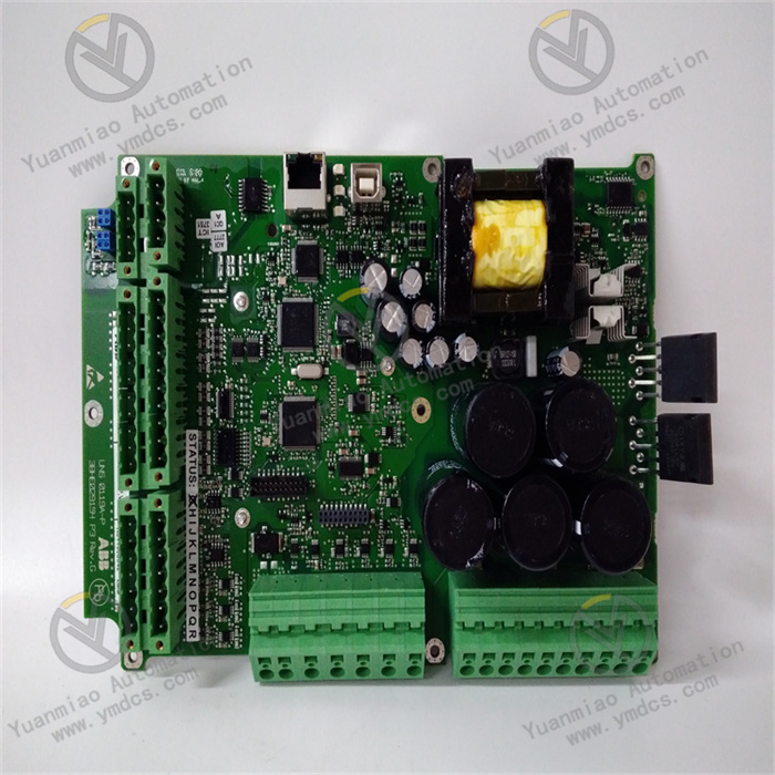
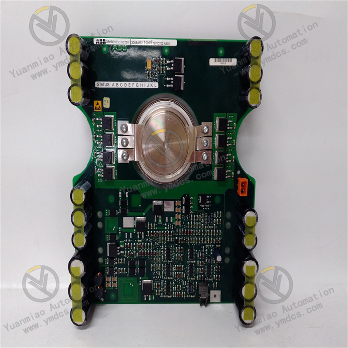
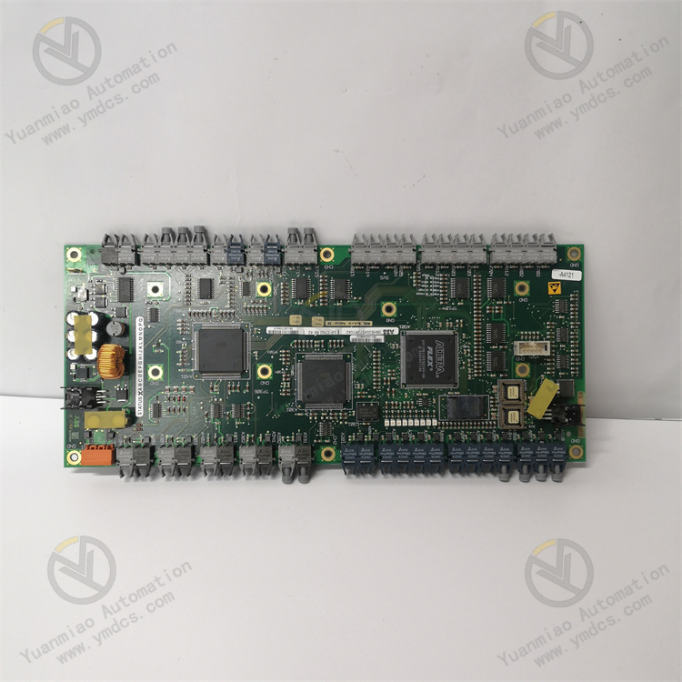
Model: UFC760BE42
Part Number: 3BHE004573R1042
Brand: ABB
Product Name: Main Control Processing Unit for UNITROL Excitation System / High‑End Excitation Controller Module
Product PositioningThe UFC760BE42 is the core main‑control module of ABB UNITROL excitation control system, serving as the computation and control hub for excitation systems of medium‑ and large‑sized synchronous generator sets. It is widely used with complete UNITROL 5000/6000 excitation equipment. As the key hardware for top‑level data computation, logic scheduling and command output of the excitation system, it undertakes core tasks including overall excitation regulation, system logic computation, data interaction, fault diagnosis and interlock protection. It is a critical spare part for stable operation of excitation systems in thermal power, hydropower, cogeneration and new‑energy power plants.
Core FunctionsIt collects comprehensive operating data including generator terminal voltage, stator current, rotor current, system reactive power, active power and frequency. High‑precision closed‑loop excitation algorithm computation is performed by high‑grade industrial processing chips. It coordinates voltage regulation, reactive power regulation, power‑factor regulation and limiting‑protection logic, and sends pulse control commands to power rectifier units for precise control of rotor excitation current. It is responsible for system communication networking, parameter storage, fault recording and event logging. It realizes no‑load voltage stabilization, grid‑connection reactive‑power matching, dynamic load regulation and fault safety protection, ensuring stable grid‑connection, accurate voltage regulation and safe operation of generator units.
Applicable SystemsFull‑range ABB UNITROL 5000 and UNITROL 6000 excitation control systems. Compatible with plant DCS systems, monitoring back‑end platforms and power‑grid dispatching systems, it can seamlessly interface with generator automatic control architectures.
Application ScenariosApplied to excitation control cabinets for synchronous generator sets in large‑scale thermal power plants, hydropower plants, biomass power stations, cogeneration plants and large industrial captive power plants. Suitable for full‑operating‑condition scenarios such as grid‑connected power generation, peak‑load and frequency regulation, steady‑state operation and fault‑disturbance recovery. Meets the 7×24‑hour continuous high‑reliability operation requirements of power equipment.
2. Technical Features
High‑Grade Industrial Main‑Control Computing PerformanceEquipped with ABB‑specialized high‑speed industrial processors featuring powerful computing capacity, high calculation accuracy and fast response. It completes excitation closed‑loop regulation calculation and multi‑logic parallel processing within millisecond level, perfectly satisfying high‑precision excitation control requirements of large‑capacity generator sets. It effectively suppresses unit voltage fluctuation and reactive‑power oscillation and guarantees unit operation quality.
Full‑Function Excitation Closed‑Loop Regulation LogicEmbedded with standardized original excitation control algorithms. Supports bumpless mode switching among Automatic Voltage Regulator (AVR), reactive‑power (VAR) regulation and power‑factor (PF) regulation. It adapts to full‑operating‑condition regulation including no‑load, grid‑connection, peak‑load adjustment, overload and system disturbance. It delivers good regulation linearity, high steady‑state accuracy and rapid dynamic response, fully complying with grid grid‑connection specifications.
Complete Multi‑Level Safety Protection MechanismIntegrates comprehensive excitation protection logics including over‑excitation limit, under‑excitation limit, rotor overcurrent, stator overcurrent, over‑/undervoltage, under‑frequency protection, loss‑of‑excitation protection and system oscillation suppression. It provides multi‑layer protection capabilities such as fault pre‑judgment, transient amplitude limiting, emergency de‑excitation, fault blocking and alarm uploading, effectively preventing severe equipment failures such as unit out‑of‑step, oscillation and burnout, and meeting high‑redundancy safety standards for power plants.
Multi‑Protocol Redundant Communication NetworkingNatively supports multiple communication protocols including Industrial Ethernet, Modbus TCP/RTU and dedicated power protocols. Dual‑link redundant communication is available. It stably interfaces with excitation slave modules, local HMI, plant DCS and remote dispatching platforms to realize remote parameter monitoring, setting modification, data uploading and remote maintenance, adapting to automated architectures of smart power plants.
Adaptability to Harsh Industrial EnvironmentsAdopts military‑grade power‑dedicated components and PCB manufacturing techniques. Built‑in power surge suppression, optoelectronic isolation and EMC electromagnetic‑compatibility filter circuits effectively resist strong electromagnetic interference from high‑voltage plant equipment, frequency converters and switchgears. It features dust‑proof, moisture‑proof, vibration‑resistant, wide‑temperature and anti‑aging properties for long‑term continuous cabinet‑mounted operation under harsh conditions.
Modular Redundant Design for Superior ReliabilitySupports active‑standby hot‑redundant operation. Upon failure of the active module, the standby module performs seamless bumpless switching without interrupting normal power generation, eliminating unit shutdown risks caused by single‑point faults. The plug‑in modular structure enables convenient disassembly and assembly without rewiring system circuits, greatly shortening maintenance‑replacement downtime.
- Visual Maintenance and Configurable AdaptabilitySupports upper‑software parameter configuration, logic editing, setting calibration and firmware upgrade. Regulation parameters and protection thresholds can be customized according to unit capacity, operating conditions and grid requirements. On‑board status LEDs and fault‑code feedback cooperate with local HMI for intuitive viewing of operating status, fault information and event records, delivering efficient commissioning and maintenance.
3. Specification Parameters
| Item | Parameter |
|---|---|
| Model | UFC760BE42 |
| Part Number | 3BHE004573R1042 |
| Device Type | Main Control Processing Unit for Generator Excitation System |
| Applicable Systems | ABB UNITROL5000 / UNITROL6000 Excitation Control System |
| Core Functions | Excitation closed‑loop regulation, logic computation, fault protection, data acquisition, communication networking, event & fault recording, parameter configuration |
| Control Modes | Adaptive multi‑mode: AVR voltage regulation, VAR reactive‑power regulation, PF power‑factor regulation |
| Supported Communication Protocols | Industrial Ethernet, Modbus TCP/RTU, dedicated power communication protocols |
| Power Supply | DC24V industrial regulated power supply |
| Rated Operating Current | 4A |
| Operating Temperature | -10℃~+60℃ |
| Storage Temperature | -25℃~+70℃ |
| Ambient Humidity | 5%~95%, non‑condensing |
| Protection Design | Optoelectronic isolation, surge suppression, EMC compliance, electromagnetic filtering, anti‑interference design |
| Operation Modes | Stand‑alone operation / Active‑standby hot‑redundant operation |
| Mounting Method | Standard cabinet card‑mounting, fixed in dedicated slots of excitation control cabinet |
| Applicable Equipment | Medium‑ and large‑sized synchronous steam‑turbine generators, hydro‑generators, biomass‑fueled generator sets |
| Dimensions | 120mm × 80mm × 40mm |
| Weight | Approx. 200g |
| Origin | Original imported from Switzerland |
| Product Characteristics | High‑speed main‑control computation, multi‑mode excitation regulation, hot‑standby redundancy, multi‑protocol communication, strong anti‑interference performance, high reliability, configurable & programmable |
4. Working Principle
Power‑On Initialization and Overall Self‑CheckAfter powered by DC24V regulated supply, the module automatically completes power‑on initialization, sequentially performing hardware chip self‑test, firmware loading, protection‑parameter import, communication‑link matching, system time synchronization and redundancy‑status detection. Passing self‑check, it establishes handshaking links with excitation power units, acquisition modules and HMI, and enters standby control state to lay a foundation for precise generator excitation control.
Multi‑Dimensional Operating‑Data Acquisition and Pre‑ProcessingThe module comprehensively receives full‑set electrical data transmitted by voltage‑and‑current sampling modules, including generator terminal voltage, stator current, rotor excitation current, system frequency, active power, reactive power and power factor. Raw signals are filtered, denoised, calibrated and pre‑processed to eliminate on‑site electromagnetic interference and restore accurate real‑time operating data of the unit.
Excitation Closed‑Loop Algorithm Calculation and Command OutputAccording to the current operating mode (voltage / reactive‑power / power‑factor regulation), measured parameters are compared in real time against rated set‑points. The original high‑precision PID closed‑loop algorithm dynamically calculates excitation‑regulation deviation values, generates accurate pulse control commands and sends them to rectifier power units. Rotor excitation current is adjusted in real time to stabilize generator terminal voltage and system reactive‑power balance and achieve zero‑error precise regulation.
Adaptive Logic Switching and Redundancy Scheduling for Full Operating ConditionsIt continuously monitors condition changes including unit start‑stop, no‑load, grid‑connection, load ramping, grid disturbance and fault impact, and automatically switches to optimal regulation logic. Active‑standby dual‑module hot‑redundant operation is supported. Upon active‑module abnormality, the standby module takes over control authority seamlessly within milliseconds and continues excitation regulation without disturbance, completely eliminating shutdown risks from single‑point failures.
- Fault Monitoring & Protection and Data TraceabilityDuring operation, it real‑time monitors various fault conditions such as excitation overcurrent, under‑excitation, over‑excitation, voltage out‑of‑range, frequency abnormality, signal loss and communication interruption. When anomalies are triggered, protective actions including excitation limiting, current reduction, output blocking and alarm uploading are executed immediately. Meanwhile, fault recording, sequential event logging and fault‑code storage are performed to preserve complete fault‑process data, providing comprehensive support for fault analysis, maintenance traceability and parameter optimization.
5. Common Faults and Troubleshooting
Phenomenon: No response after module power‑on, indicator lamps off, system fails to recognize the modulePossible Causes
① Loss of DC24V power supply, low voltage or reversed polarity;
② Poor contact of module slot, oxidized and dust‑covered gold‑finger contacts;
③ Damaged internal power circuit of the module, lost or crashed firmware.
Troubleshooting
Power off the system and allow sufficient discharge. Measure DC24V supply voltage and polarity, check power‑circuit breakers and circuit continuity. Extract the module, clean gold‑finger contacts and slot dust, then re‑insert and fix steadily. Re‑flash matching firmware. If no response persists with normal power supply and wiring, hardware failure of the module is confirmed; replace with original spare part.
Phenomenon: Severe fluctuation of unit voltage and reactive power, slow excitation‑regulation response and poor accuracyPossible Causes
① Improper matching of regulation gain and integral parameters, parameter drift;
② Mis‑judged regulation caused by abnormal sampling data;
③ Aging main‑control computing circuit of the module, delayed algorithm response;
④ On‑site electromagnetic interference distorts data computation.
Troubleshooting
Inspect sampling‑circuit wiring and shielding grounding to eliminate electromagnetic interference. Access system back‑end to recalibrate excitation‑regulation PID parameters, voltage‑stabilization thresholds and reactive‑power limit parameters, and optimize regulation logic. Stabilize unit load conditions. If fluctuation remains after parameter optimization, main‑control accuracy failure is confirmed; replace the module.
Phenomenon: Frequent alarms of excitation over‑excitation / under‑excitation and overcurrent protectionPossible Causes
① Improper or disordered protection threshold settings;
② Protection mis‑judgment caused by sampling‑signal deviation;
③ Disordered protection logic or abnormal firmware inside the module;
④ Grid‑voltage disturbance surges.
Troubleshooting
Verify and correct thresholds for over‑excitation, under‑excitation, rotor overcurrent and voltage protection to match unit rated conditions. Calibrate sampling‑circuit accuracy and eliminate signal deviation. Reboot the module to reset firmware and restore original standard configuration. Mitigate grid‑disturbance impacts. If alarms persist, module failure is confirmed; replace spare part.
Phenomenon: Module communication interruption, no data at back‑end, remote control invalidPossible Causes
① Loose or damaged communication cables, poor interface contact;
② Mismatched communication address, baud rate or protocol parameters between module and system;
③ Aged communication chip or faulty communication circuit of the module.
Troubleshooting
Inspect communication cables and port connectors, re‑plug and fasten connections, replace damaged cables. Verify and unify communication parameters, protocol types and device addresses between module and system. Check network‑switch and link status. If disconnection continues with correct configuration, communication hardware failure is confirmed; replace the module.
Phenomenon: Abnormal active‑standby module switching, redundant function failurePossible Causes
① Inconsistent parameters and mismatched firmware versions between active and standby modules;
② Abnormal redundant synchronous‑communication link;
③ Faulty module redundancy logic, damaged hardware synchronization circuit.
Troubleshooting
Unify firmware versions and full‑set operating parameters for active and standby modules. Inspect redundant synchronous‑communication cables and repair link faults. Re‑configure redundancy‑switching logic and test switching performance. If switching still fails with sound synchronization links and correct parameters, hardware failure is confirmed; replace with original module.
Phenomenon: High module operating temperature, frequent crash and restart, unstable operationPossible Causes
① Blocked cabinet air duct, heavy dust accumulation and poor heat dissipation;
② Abnormal power consumption from component aging due to long‑term high‑load computation;
③ Excessive supply‑voltage fluctuation and severe power‑ripple interference;
④ Stuck or abnormal firmware.
Troubleshooting
Clean cabinet air ducts and module surface dust, improve ventilation and heat dissipation, and control cabinet ambient temperature. Optimize DC24V power quality and install filters to stabilize power supply. Re‑flash stable original‑factory firmware. If faults recur continuously, module aging failure is confirmed; replace spare part in advance to avoid shutdown risks.