Description
1. Product Overview
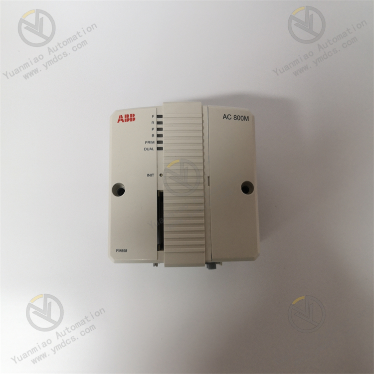
Model: PM858
Material No.: 3BSE093350R1
Brand: ABB
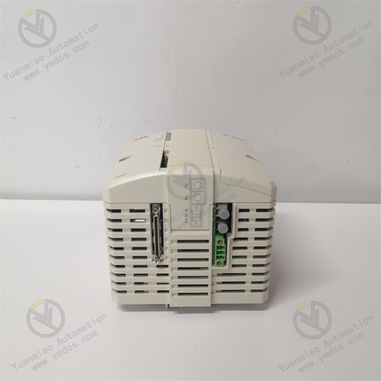
Product Name: AC800M High‑Performance CPU Main Unit / Process Controller Module
Product PositioningPM858 is a high‑end core CPU module for ABB Ability System 800xA DCS. As the high‑performance computing core of AC800M controller series, it serves as the central hub for logic computation, process scheduling, data processing and command output of the whole industrial automation control system. Designed for medium‑to‑large‑scale complex‑process scenarios such as power, chemical and metallurgical industries, it undertakes critical tasks including core control computation, I/O data coordination, field‑bus communication management, process interlock protection and equipment linkage scheduling. It is an essential spare part to guarantee high‑precision, high‑reliability and non‑stop operation of industrial control systems.
Core FunctionsAs the top‑level control core of DCS system, it adopts high‑performance industrial processor to centrally execute plant‑wide process logic, closed‑loop regulation calculation, sequence control and batch recipe control. It coordinates bidirectional data interaction among S800 I/O, field smart devices and upper‑level monitoring system, and accurately delivers process control and interlock action commands. Built‑in complete control algorithms and fault‑protection logic support multi‑task parallel computation and millisecond‑level cycle control. It stably meets stringent control requirements of complex working conditions, high‑frequency regulation and interlock linkage, effectively avoiding risks of process runaway, equipment mis‑operation and production shutdown, and ensures 7×24‑hour continuous stable operation of the whole automation system.
Applicable SystemsABB Ability System 800xA distributed control system and full‑range AC800M controller architecture. Fully compatible with S800 distributed I/O system, field‑bus modules, HMI and upper‑level monitoring & scheduling platform. It can be seamlessly integrated into the complete ABB industrial automation control system and supports compatible capacity expansion, retrofitting and replacement for new and legacy systems.
Application ScenariosWidely deployed in high‑end automatic production lines including thermal power plants, hydropower plants, cogeneration plants, petrochemical plants, fine‑chemical plants, metallurgy & mining, building‑material plants and large‑scale industrial captive power stations. Suitable for installation in central‑control main cabinets and core control sub‑stations. Designed for industrial process control scenarios requiring complex workflows, high‑precision regulation, high safety redundancy and zero downtime.
2. Technical Features
High‑Performance Industrial Multi‑Core Computing with Superior Real‑Time Control AccuracyEquipped with ABB proprietary high‑end industrial multi‑core processor with powerful computing capability and fast processing speed. It supports minimum 1 ms high‑speed control cycle and can process multi‑task logic computation, PID closed‑loop regulation, sequence control and batch recipe calculation in parallel. It satisfies computing demands of massive I/O points, complex interlock logics and high‑frequency process regulation for large‑scale plants. Computation is lag‑free with high control precision, which greatly improves process stability and product yield.
Complete Industrial Control Algorithm Library for Full‑Scenario Process AdaptationBuilt‑in standardized industrial control algorithm library integrates optimized regulation algorithms such as anti‑windup PID, derivative‑first PID and adaptive PID. It supports continuous process control, discrete sequence control, SFC step logic and ISA S88.01 standard batch recipe control for multi‑level recipe management and fast process switching. It realizes self‑adaptive control under full working conditions including no‑load, steady‑state, load‑variation, fault disturbance and start‑stop transition, and perfectly fits complex production processes in multiple industries.
CPU Redundant Hot‑Standby Architecture to Eliminate Single‑Point FailureNatively supports dual‑CPU active‑standby hot‑standby mode. The primary and standby modules realize real‑time synchronization of data, logic and parameters. When the primary CPU suffers hardware failure, program exception or communication loss, the standby module takes over full control authority via millisecond‑level bumpless switchover without process interruption, equipment mis‑operation or production shutdown. It meets design standards of high redundancy, high safety and high availability for high‑end industrial applications.
Multi‑Bus & Multi‑Protocol Compatibility with Powerful Networking CapabilityIntegrated dual Gigabit Ethernet ports. Natively supports ABB dedicated control protocol, Modbus TCP/RTU, Industrial Ethernet and other mainstream industrial protocols, and is compatible with CEX bus and field‑bus networking architecture. It connects I/O sub‑stations, local field devices, upper‑level monitoring system and remote scheduling system simultaneously. Parallel multi‑link data transmission delivers flexible networking, large throughput and high communication stability, suitable for multi‑layer networking of smart factories.
ECC‑Enabled Data Storage for High‑Reliable Data ManagementHigh‑speed storage unit with ECC error‑checking and error‑correction function identifies and corrects occasional errors during data transmission and storage in real‑time, preventing data corruption, parameter drift and logic misjudgment. It supports long‑term stable storage of programs, parameters, fault logs and event records to guarantee data integrity and accuracy during long‑term system operation.
Adaptable to Harsh Industrial Environments with Excellent Anti‑Interference PerformanceAdopts industrial‑grade robust components and high‑standard PCB technology. Built‑in opto‑electric isolation, surge suppression and EMC filtering circuits effectively resist high‑voltage pulses, inverter harmonics, heavy electromagnetic radiation and ground‑loop interference on‑site. It features dust resistance, moisture resistance, wide temperature tolerance, vibration resistance and anti‑aging capability for long‑term heavy‑duty cabinet‑mounted operation.
- Intelligent Visualized Operation & Maintenance for Convenient Configuration and CommissioningSupports online configuration, logic editing, parameter calibration, firmware upgrade and remote maintenance via upper‑level software. Control logic, regulation parameters and interlock thresholds can be customized according to process requirements. On‑board LED indicators intuitively display operation, communication, fault and redundancy status. Combined with system background, fault codes, event timestamps and operation logs can be traced precisely to reduce maintenance workload and troubleshooting time.
3. Specification Parameters
| Item | Parameter |
|---|---|
| Model | PM858 |
| Material Code | 3BSE093350R1 |
| Device Type | AC800M series DCS main CPU module, process control unit |
| Applicable System | ABB Ability System 800xA DCS, AC800M controller architecture, S800 I/O distributed system |
| Core Functions | Process logic computation, PID closed‑loop regulation, sequence / batch control, multi‑protocol communication networking, I/O data coordination, redundant hot‑standby control, fault self‑diagnosis, data storage & tracing |
| Processor Performance | High‑end industrial multi‑core processor, minimum 1 ms high‑speed control cycle |
| Storage Feature | ECC‑enabled memory, long‑term firmware storage, support for event & fault oscillographic recording |
| Communication Ports | Dual RJ45 Gigabit Ethernet ports, redundant networking supported |
| Supported Protocols | ABB dedicated control protocol, Modbus TCP/RTU, Industrial Ethernet protocol |
| Control Task Capacity | Single controller supports 32 tasks with 32 different‑cycle parallel tasks |
| Power Supply | DC24V industrial regulated power (±20% wide‑voltage tolerance) |
| Operating Temperature | -20℃~+70℃ |
| Storage Temperature | -40℃~+85℃ |
| Ambient Humidity | 5%~95%, non‑condensing |
| Protection Features | Opto‑electric isolation, surge suppression, EMC compliance, short‑circuit & over‑current protection, ECC data error correction |
| Operation Mode | Stand‑alone operation, active‑standby CPU redundant hot‑standby with bumpless switchover |
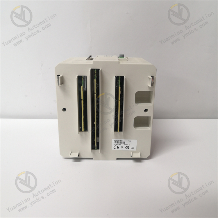
| Mounting Method | Standard cabinet card‑mounting, fixed on dedicated controller base |
| Compliance Standards | Industrial IEC safety standard, EMC certification, CE/UL industrial certification |
| Origin | Original imported from Switzerland |
| Product Characteristics | High‑speed multi‑core computing, millisecond‑level control cycle, CPU redundancy & fault tolerance, ECC data correction, multi‑protocol networking, strong anti‑interference, full‑process adaptability, intelligent self‑diagnosis, low‑frequency maintenance |
4. Working Principle
Power‑On Initialization and Overall Self‑TestAfter powered by regulated DC24V supply, the module completes automatic initialization, sequentially performing hardware chip self‑test, firmware loading, system‑parameter import, communication‑port initialization, bus‑link matching, redundancy‑status verification and system clock synchronization. It comprehensively detects hardware faults, program exceptions, parameter errors and link failures. Upon passing self‑test, handshakes with I/O modules, communication modules and upper‑level system are established, and the module enters normal control status.
Global Data Acquisition and Pre‑ProcessingAs the computing core, the CPU receives field data including analog signals, digital signals, equipment status, process parameters and grid parameters in real‑time. Raw signals are filtered, denoised, calibrated and pre‑processed. ECC function corrects transmission errors and rejects abnormal data caused by electromagnetic interference to restore accurate real‑time process conditions, providing reliable data foundation for subsequent logic computation and regulation.
Multi‑Task Parallel Logic Computation and Precise ControlBased on pre‑configured process logic and control program, it executes multiple tasks in parallel: PID closed‑loop regulation, sequential step control, batch recipe control, interlock logic judgment and over‑limit protection calculation. Measured process parameters are compared with set thresholds dynamically. Accurate regulation commands, switching commands and interlock protection commands are output to actuators and I/O units to realize steady‑state parameter stabilization, dynamic load adjustment, equipment linkage and fault safety protection.
Dual‑CPU Redundancy Synchronization and Bumpless SwitchoverUnder redundant mode, primary and standby CPU modules run programs, logic, process parameters and data status synchronously with consistent data mirroring and timing. The system continuously monitors operating status, computation performance and communication links of primary CPU. In case of primary‑module failure, the standby module takes over full control within milliseconds without data loss, logic interruption or process disturbance, eliminating risks of system shutdown and process runaway caused by single‑CPU failure.
- Data Maintenance and Fault Tracing ProtectionDuring operation, system logs, process operation records, equipment status changes and fault alarms are continuously recorded. Fault timestamps, oscillographic data and fault codes are stored automatically. Hardware overload, communication anomalies, program stalling and parameter drift are monitored in real‑time. Once an abnormality is detected, interlock protection, alarm upload and fault blocking are triggered immediately. Complete historical data is retained for maintenance troubleshooting, fault tracing and process optimization.
5. Common Faults and Troubleshooting
Phenomenon: No LED after power‑on, CPU unrecognized by system, main controller offlinePossible Causes
① Loss of DC24V power supply, excessive voltage deviation, reversed polarity or large power‑supply ripple;
② Poor contact between module and base, oxidized & dusty gold‑fingers or loose slot;
③ Damaged controller base or abnormal bus circuit;
④ Damaged internal main chip, lost or crashed firmware.
Troubleshooting
Power off the system for full discharge. Measure DC24V voltage, polarity and circuit continuity; inspect circuit breakers, wiring and terminal tightness. Extract the module, clean gold‑fingers and slot dust, then re‑insert firmly. Re‑flash original‑factory firmware and restore system configuration. If no response persists with normal power and connection, hardware failure is confirmed; replace with original spare part.
Phenomenon: Severe process‑parameter fluctuation, slow regulation and degraded control accuracyPossible Causes
① Improper PID parameters or control‑cycle ratio, long‑term parameter drift;
② Incorrect logic configuration, abnormal task allocation and computation lag;
③ Distorted sampling data and misjudgment caused by severe on‑site electromagnetic interference;
④ Degraded CPU computing performance and task processing congestion.
Troubleshooting
Check shielding and grounding to eliminate electromagnetic interference on sampled data. Calibrate PID parameters, control cycles and interlock thresholds via system background, and optimize task‑scheduling logic. Remove redundant program segments to reduce CPU load. If faults remain after parameter and logic optimization, module performance degradation is confirmed; replace the CPU module.
Phenomenon: Abnormal CPU redundant switchover and failed active‑standby synchronizationPossible Causes
① Inconsistent firmware versions or operating parameters between primary and standby CPU;
② Faulty redundant synchronization bus or loose communication links;
③ Missing redundancy‑configuration parameters or incorrect switchover‑logic settings;
④ Damaged hardware circuit for module redundant synchronization.
Troubleshooting
Unify firmware versions as well as full‑set process, communication and redundancy parameters for primary and standby CPU. Inspect redundant‑synchronization bus and interfaces and repair faulty links. Re‑configure redundant‑switchover logic and test bumpless switchover by fault simulation. If switchover still fails with correct parameters and links, hardware failure is confirmed; replace the module immediately to guarantee system redundancy safety.
Phenomenon: Frequent system communication interruption, offline I/O points and packet lossPossible Causes
① Aged Ethernet cable, poor RJ45 contact or faulty networking links;
② Conflicting or misconfigured communication protocols, IP addresses and port parameters;
③ Abnormal CPU communication processing circuit and congested data forwarding;
④ Network bandwidth congestion and task overload leading to data‑processing timeout.
Troubleshooting
Fully inspect communication cables and ports, replace worn‑out cables and tighten connectors. Verify and unify networking parameters, communication protocols and device addresses; eliminate network conflicts and loops. Optimize CPU task allocation to release network bandwidth. If communication anomalies persist with correct networking settings, module communication‑circuit failure is confirmed; replace with original module.
Phenomenon: Excessively high module temperature, frequent crash & restart and unstable system operationPossible Causes
① Blocked cabinet air duct, heavy dust accumulation and poor heat dissipation;
② Long‑term heavy‑load multi‑task computation and abnormal power consumption under full chip load;
③ Large power‑supply voltage fluctuation and severe power‑supply interference;
④ Stuck, incompatible or over‑loaded firmware.
Troubleshooting
Thoroughly clean cabinet air duct and module surface dust, improve ventilation and stabilize cabinet ambient temperature. Optimize DC24V power quality and install filters to suppress power‑supply ripple. Remove invalid program tasks and flash stable original‑factory firmware. If faults recur continuously, module aging failure is confirmed; replace spare part in advance to avoid system‑shutdown risks.
Phenomenon: False interlock triggering, abnormal logic execution and disordered process actionsPossible Causes
① Misconfigured or drifted interlock thresholds and logic parameters;
② Data misjudgment caused by sampling abnormality and ECC‑correction failure;
③ Disordered CPU logic computation and program exceptions;
④ Instantaneous data anomaly triggering protection due to external interference.
Troubleshooting
Verify interlock logic, protection thresholds and process parameters item‑by‑item and correct mis‑configurations. Check sampling‑loop accuracy, eliminate data anomalies and restore ECC function. Reboot the module for reset and restore factory‑standard configuration. Remove external interference risks. If logic still operates abnormally, module failure is confirmed; replace spare part timely.