Description
1. Product Overview
Full Model: DTCC901B 61430001-FU
Manufacturer: ABB (ABB Group, Switzerland)
Product Series: High-end Communication Control Module Series for Advant OCS / Industrial IT Process Control System
Product Name: Multi-Interface High-Speed Communication Control Module, Industrial Bus Data Processing Module
Product Positioning
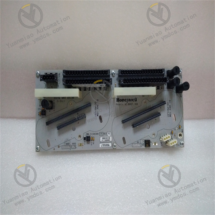
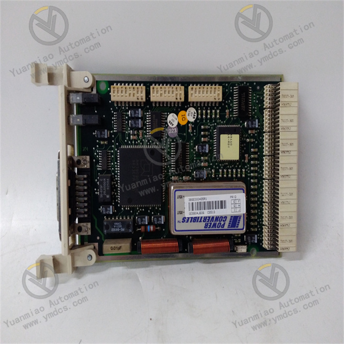
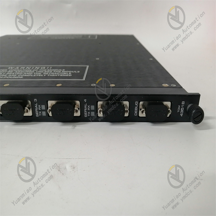
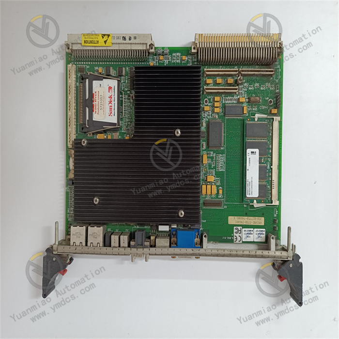
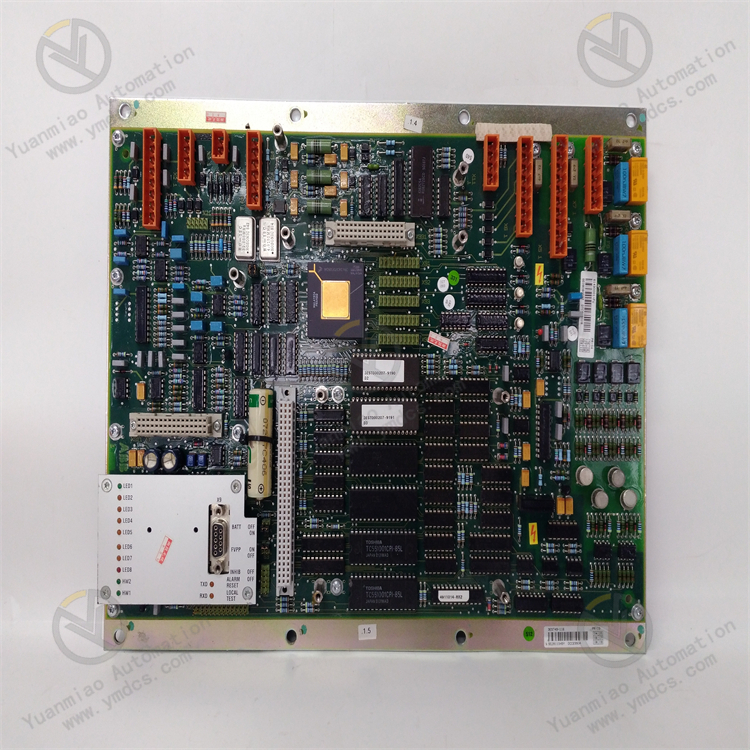
DTCC901B 61430001-FU is a high-performance multi-interface communication control module supporting ABB industrial automation control systems. It serves as the core unit for data exchange, bus scheduling and peripheral expansion of the whole automation system. Integrated with multiple types of industrial high-speed communication interfaces, the module integrates functions including data parsing, protocol conversion, link scheduling and coordinated peripheral control. It is mainly responsible for high-capacity, low-latency data transmission and interaction between the system main controller, field intelligent devices, upper monitoring system and third-party peripherals. Adopting industrial high-speed bus processor and multi-stage electrical isolation architecture, it can operate stably under harsh industrial conditions in power plants, chemical plants, metallurgical sites featuring intensive electromagnetic interference, fluctuating temperature & humidity and long-term continuous operation. It ensures stable cross-device and cross-system data communication, reliable links and controllable delay. As core hardware for network expansion, communication link redundancy upgrade and intelligent peripheral expansion of large and medium-sized industrial DCS and PLC automation systems, it is widely applied in new unit engineering, communication retrofitting of legacy systems, bus architecture optimization and iterative upgrading of industrial automation systems.
Core Functions
The module performs six core functions: multi-protocol bus communication interaction, high-speed data transceiving and parsing, redundant communication link scheduling, protocol adaptation for third-party devices, peripheral expansion control and communication fault self-diagnosis. Equipped with Ethernet, RS485, CAN and optical fiber communication interfaces, it can simultaneously connect upper SCADA monitoring systems, field smart instruments, variable frequency drives, serial peripherals, optical fiber remote terminals and other equipment. It automatically completes parsing, conversion and sorting of different communication protocols, realizing command distribution, status feedback, parameter interaction and real-time data uploading between the main control system and peripherals. Built-in surge protection, link fault tolerance and automatic reconnection mechanisms effectively avoid communication stagnation, data loss and link interruption caused by on-site electromagnetic interference, line fluctuation and transient disconnection. It guarantees accurate command transmission, real-time data interaction and synchronized equipment linkage for the whole automation system, and supports stable operation of system sequence control, interlock, data monitoring and remote regulation.
Compatible Systems
Fully compatible with the complete ABB Advant OCS and Industrial IT process control systems, supporting the standard rack bus architecture of the system. It can seamlessly network with system main control CPUs, I/O acquisition modules, power supply modules and other communication modules. Natively compatible with all versions of ABB Control Builder configuration software, supporting customized communication protocol configuration, link parameter debugging, port authority setting and online communication status monitoring. The module supports non-destructive in-situ replacement with full backward compatibility for new and legacy systems. No modification to main control logic and core programs is required; only communication parameter matching is needed for commissioning. It adapts to various industrial scenarios including replacement of aging communication modules in old systems, bus architecture upgrade, multi-device network expansion and reconstruction for third-party equipment connection.
Application Scenarios
Mainly deployed in industrial sites equipped with ABB control systems, including thermal power, hydropower, wind power, oil & gas chemical industry, metallurgy heavy industry, large intelligent manufacturing production lines and municipal energy automation systems. It focuses on core working conditions such as cross-system data exchange, bus networking of intelligent instruments, communication linkage of variable frequency equipment, remote optical fiber data transmission, serial peripheral expansion and upper monitoring data interconnection. Capable of long-term operation under severe environments with high temperature, dust, mechanical vibration, intensive frequency conversion electromagnetic interference, voltage fluctuation and alternating temperature & humidity, it provides core hardware support for high-speed, stable and reliable bus communication and equipment linkage of industrial automation systems, ensuring continuous, safe and efficient production.
2. Technical Features
Integrated Multi-Interface Design with Powerful Networking Expansion Capability
A single module integrates mainstream industrial communication interfaces including Gigabit adaptive Ethernet, high-speed RS485, CAN bus and optical fiber ports, covering full scenarios of wired, bus and long-distance optical transmission. It supports multi-channel parallel communication and synchronous networking of multiple devices and protocols without additional communication expansion modules, which greatly saves rack slot resources and hardware costs. It meets the demands of centralized networking of numerous devices, cross-region remote communication and multi-system data interconnection in complex industrial systems.
High-Speed Data Transmission with Excellent Real-Time Performance and Throughput
Equipped with industrial high-speed communication processor. Ethernet ports support 10/100/1000 Mbps auto-negotiation transmission, and bus ports support high-frequency and high-speed data transceiving for fast parsing of massive real-time data, equipment operating parameters and control commands. It achieves ultra-low transmission delay and large throughput, satisfying strict real-time requirements of high-precision coordinated control, high-frequency data acquisition and remote real-time regulation without command lag, data congestion or update delay.
Wide Multi-Protocol Compatibility for Convenient Cross-Device Connection
Natively compatible with mainstream industrial communication protocols including Modbus RTU/TCP, CAN bus protocol, industrial Ethernet protocol and general serial protocols, supporting customized configuration and bidirectional protocol conversion. It can seamlessly connect native ABB equipment as well as third-party PLCs, smart instruments, inverters, remote terminals and serial peripherals, breaking communication barriers between devices of different brands and protocols. It significantly improves system compatibility and expandability and fits retrofitting projects integrating multi-brand equipment in legacy systems.
Multi-Stage Isolation Protection with Superior Anti-Interference Performance
All communication ports adopt independent electrical isolation design to prevent crosstalk between ports. Multiple protection circuits including surge suppression, electrostatic protection, pulse interference filtering and electromagnetic shielding are embedded. It effectively resists high-frequency interference from inverters, electromagnetic radiation of high-voltage equipment, line surge impact and electrostatic coupling interference, fully complying with industrial EMC standards. Communication links remain stable under complex operating conditions without data loss, intermittent disconnection or transmission error codes.
Intelligent Link Fault Tolerance for Enhanced Communication Stability
Built-in mechanisms including intelligent link monitoring, automatic reconnection after disconnection, data fault-tolerant verification and link redundant scheduling. It identifies link anomalies, data loss and command timeout in real time, automatically performs error correction, data retransmission and link restart. It minimizes communication failures triggered by transient line fluctuation and electromagnetic interference. Multi-link load balancing and redundant backup are supported to ensure uninterrupted transmission of critical control commands and monitoring data.
Visual Full-Range Self-Diagnosis for Efficient Operation & Maintenance
Three-tier self-diagnosis covering module level, port level and link level. It continuously monitors potential risks including module power status, chip operating condition, communication rate of each port, link connectivity, data error rate and protocol mismatch. Status indicator lights are arranged on the panel for direct observation of real-time operating status of each port. Fault information is uploaded to the upper system to accurately locate faulty ports and anomaly types, eliminating full-link inspection and drastically shortening troubleshooting time.
Industrial Ruggedized Design Ensuring Reliable Long-Term Operation
Constructed with industrial reinforced PCB and wide-temperature anti-aging components, enhanced with moisture-proof, dust-proof, oxidation-resistant, vibration-proof and shock-resistant processes for high overall protection. Adaptable to harsh industrial environments with alternating high/low temperature, dust, humidity and continuous mechanical vibration. It achieves excellent MTBF and supports 24/7 uninterrupted communication operation without port performance degradation, protocol drift or link failure after long-term running.
3. Specification Parameters
| Item | Parameter |
|---|---|
| Model | DTCC901B 61430001-FU |
| Manufacturer | ABB (ABB Group, Switzerland) |
| Product Series | Communication Control Module for Advant OCS / Industrial IT Control System |
| Product Type | Multi-Interface High-Speed Communication Control Module, Industrial Bus Data Processing Module |
| Applicable System | Complete ABB Advant OCS and Industrial IT Process Control Systems |
| Configuration Software | All versions of ABB Control Builder |
| Hardware Interfaces | 4 × Gigabit Ethernet, 4 × RS485, 3 × CAN Bus, 2 × Optical Fiber Communication Ports |
| Ethernet Rate | 10/100/1000 Mbps Auto-Negotiation |
| Supported Protocols | Modbus RTU/TCP, CAN Bus Protocol, Industrial Ethernet Protocol, General Serial Protocol (Customizable) |
| Communication Features | Multi-port parallel communication, bidirectional protocol conversion, link fault tolerance, auto reconnection, data verification & error correction |
| Isolation Performance | Independent electrical isolation for each port, common-mode interference resistance, anti-crosstalk between ports, high-voltage electrostatic isolation protection |
| EMC Immunity | Compliant with industrial EMC standards; resistant to inverter interference, surge impact, electrostatic discharge and high-frequency radiation interference |
| System Power Supply | DC24V industrial power supply; applicable range DC20.4V~27.6V (±15% wide voltage tolerance) |
| Power Consumption | Standby ≤4W; Full load ≤20W |
| Operating Temperature | -20℃~+60℃ |
| Storage Temperature | -40℃~+85℃ |
| Ambient Humidity | 5%~95%RH, non-condensing; suitable for humid and dusty industrial sites |
| Protection Class | IP65 (Module body) |
| Mounting Method | Snap-in installation on standard system rack slots |
| Dimension | 100mm × 100mm × 50mm |
| Weight | Approx. 0.5kg |
| O&M Features | Three-tier full-range self-diagnosis, visual port status, online parameter configuration, hot-swappable in-situ replacement, precise fault localization |
| Product Characteristics | Multi-interface integration, high-speed transmission, multi-protocol compatibility, strong anti-interference, stable links, high fault tolerance, convenient maintenance |
4. Working Principle
4.1 Power-On Initialization and Full-Range Self-Test
After stable DC24V power supply from the system, the module automatically completes hardware initialization, communication chip startup, underlying protocol loading, bus parameter reset and rack bus protocol matching. It performs comprehensive self-test on power loops, main processing chip, all communication ports, isolation circuits and fault diagnosis units sequentially to detect hidden risks such as port short circuit, line anomaly, chip failure, protocol loading failure and bus disconnection. Upon successful self-test, it synchronizes system communication configuration parameters, port protocol settings, baud rate and address parameters automatically, completes link adaptation calibration and enters steady-state high-speed communication and data interaction mode.
4.2 Multi-Port Signal Access and Isolation Preprocessing
Upper monitoring equipment, field smart instruments, variable frequency drives, remote terminals and other peripherals connect to the module via Ethernet, RS485, CAN and optical fiber ports respectively. All incoming communication data and control commands first pass through independent port isolation circuits and voltage stabilizing filtering units to filter high-frequency line noise, surge pulses and electrostatic interference, regularize signal waveforms, block inter-port crosstalk and external electromagnetic interference. Pure original communication data is guaranteed to lay a foundation for subsequent data parsing and transmission.
4.3 Multi-Protocol Parsing and Bidirectional Data Conversion
The core processor of the module receives parallel communication data from each port in real time, automatically identifies corresponding communication protocols according to preset configuration parameters, and completes data decoding, command parsing and data verification. For communication data from equipment with different protocols and brands, bidirectional protocol conversion and data formatting are executed. Data from peripherals is uniformly converted into formats recognizable by the main control system. Meanwhile, control commands issued by the system are converted into protocol formats matching peripherals, breaking communication barriers across different devices and systems.
4.4 Intelligent Link Scheduling and Fault-Tolerant Transmission
Equipped with intelligent link scheduling mechanism, the module dynamically allocates transmission bandwidth according to communication load of each port to realize stable multi-port parallel transmission. Integrity of each data frame is verified continuously. In response to data loss, error codes and command timeout, automatic data retransmission, command supplement and link restart are executed. The multi-link redundant architecture supports automatic switching of faulty links, avoiding communication interruption caused by transient line fluctuation and interference, and ensuring uninterrupted stable transmission of critical control and monitoring data.
4.5 Data Aggregation Upload and Command Execution
Sorted field equipment operating data, status parameters and fault information are aggregated and uploaded to the system main control CPU in real time through the rack high-speed bus, and written into the system data image area. The data can be called by upper SCADA systems for real-time monitoring, data storage, trend analysis and fault alarming. Meanwhile, control commands, parameter adjustment instructions and equipment linkage commands issued by the system are accurately received. After protocol conversion, commands are distributed to corresponding field peripherals to realize remote regulation and logic linkage of field equipment by the control system.
4.6 Real-Time Fault Diagnosis and Status Tracing
The module runs three-tier self-diagnosis throughout operation, continuously monitoring module supply voltage, chip operating temperature, link status of each port, communication rate, data error rate and protocol matching status. It accurately identifies various faults including port failure, line disconnection, protocol mismatch, abnormal data transmission, chip operating anomaly and link congestion. Corresponding port alarm indicators light up synchronously, fault codes are generated and uploaded to the upper system. Real-time alarm, precise localization and full traceability of communication faults are realized, enabling maintenance personnel to quickly handle communication anomalies and restore normal system networking.
5. Common Faults and Troubleshooting
5.1 Symptom: No response after power-on; module undetected by system, offline status
Possible Causes
① The module is not fully locked into the rack; poor contact caused by loose or oxidized backplane contacts with dust accumulation;
② Abnormal or under-voltage power supply of the rack backplane;
③ Mismatched firmware versions between module and control system;
④ Loss of module bus protocol parameters and abnormal initialization;
⑤ Damage to internal main power circuit or bus communication chip of the module.
Solutions
Power off the system, reinsert and lock the module fully. Clean oxide layer and dust on backplane contacts with anhydrous alcohol to ensure good contact. Measure DC24V supply voltage of the rack with multimeter, troubleshoot power module faults and stabilize voltage within standard range. Check firmware versions of module and system and upgrade to compatible releases. Re-download communication configuration parameters of the module and reconfigure after factory reset. If the module remains undetected after eliminating external power supply, contact and firmware issues, internal hardware failure is confirmed. Replace with original DTCC901B 61430001-FU module.
5.2 Symptom: Single-port communication interruption, link disconnected, peripheral offline
Possible Causes
① Broken communication cable, loose connector, oxidized and poor contact of RJ45 terminals/screw terminals for the corresponding port;
② Mismatch between port configuration (protocol, baud rate, device address) and peripheral parameters;
③ Fault of external equipment or damaged peripheral communication unit leading to no data exchange;
④ Port circuit locked by overload or transient surge protection;
⑤ Aging and damage of single-port isolation circuit or transmission chip inside the module.
Solutions
Inspect communication cables of the faulty port section by section, remake connectors, fasten terminals and replace damaged cables. Verify port communication parameters to match peripheral protocol, baud rate and device address, then re-download configuration. Test communication function of external equipment separately and repair or replace faulty peripherals. Power cycle the module to release port protection lock and reset port parameters. If the port stays offline after parameter and line inspection, single-port hardware damage is confirmed and module replacement is required.
5.3 Symptom: Communication data loss, garbled codes, abnormal data refresh
Possible Causes
① Severe on-site electromagnetic interference; unshielded cables or non-standard grounding;
② Excessively long communication cables, impedance mismatch leading to serious signal attenuation;
③ Excessively high port baud rate exceeding transmission capacity of cables;
④ Overloaded multi-port communication resulting in link congestion;
⑤ Aging of port filtering and verification circuits of the module with degraded anti-interference capability.
Solutions
Replace with shielded communication cables and implement standardized single-point grounding. Route communication cables away from strong interference sources such as inverters and high-power motors. Shorten transmission distance or install signal repeaters to match line impedance. Appropriately reduce port baud rate and optimize data frame format. Reasonably allocate communication load of each port to avoid link congestion. Enable mandatory data verification and retransmission mechanism of the system. If data disorder persists after optimization, circuit aging of the module is confirmed and spare part replacement is needed.
5.4 Symptom: Frequent intermittent disconnection, repeated reconnection and unstable communication
Possible Causes
① Large fluctuation of system supply voltage leading to unstable working voltage of the module;
② Poor contact of communication cables and transient disconnection caused by wire vibration;
③ Abnormal ambient temperature & humidity; insulation degradation due to condensation and dust accumulation on module ports;
⑤ Improper link fault tolerance parameters with low disconnection threshold;
⑤ Drifted operating status of the main communication chip of the module.
Solutions
Optimize cabinet power supply and install voltage stabilizing filtering equipment to stabilize DC24V working voltage. Fully inspect and fasten all communication connectors and fix wiring to avoid shaking. Clean dust on module ports and improve cabinet temperature & humidity to prevent condensation and moisture. Optimize link fault tolerance, disconnection judgment and reconnection delay parameters to enhance link stability. If intermittent disconnection still occurs after all rectification, hardware performance degradation of the module is confirmed and original module replacement is required.
5.5 Symptom: Abnormal multi-protocol conversion; failure to connect third-party equipment
Possible Causes
① Incorrect module protocol configuration; corresponding protocol function not enabled;
② Mismatched communication parameters between third-party equipment and the module;
③ Abnormal protocol conversion program of the module; missing protocol adaptation packages in firmware;
④ Incomplete data transmission caused by port isolation failure;
⑤ Conflicting device addresses and chaotic bus networking logic.
Solutions
Re-enter configuration software, enable protocol functions of corresponding ports and correct configuration parameters. Align baud rate, parity bit, address and frame format between peripherals and the module to ensure consistency on both sides. Upgrade module firmware and supplement protocol adaptation packages for target third-party equipment. Inspect operating status of port isolation circuits and fix transmission anomalies. Sort out bus networking architecture, modify conflicting device addresses and optimize networking logic. If interconnection cannot be realized after configuration and networking rectification, hardware failure of the protocol processing unit is confirmed and module replacement is required.