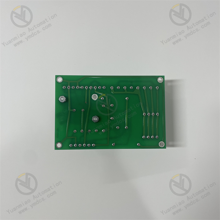
Description
1. Overview
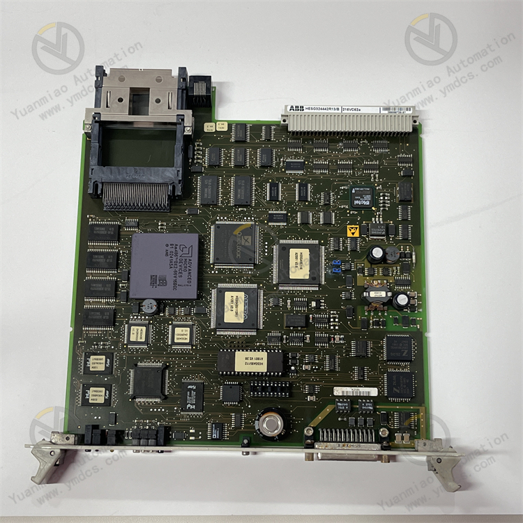
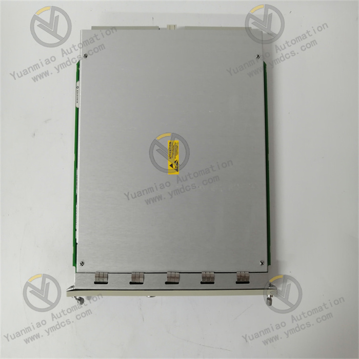
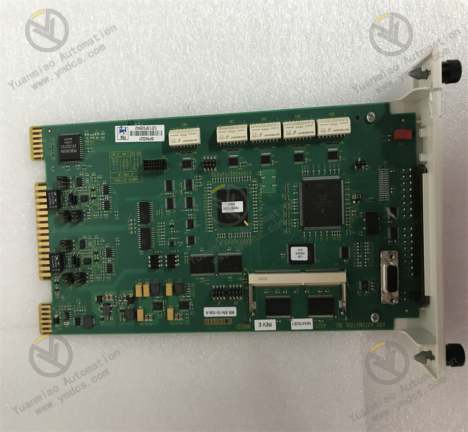
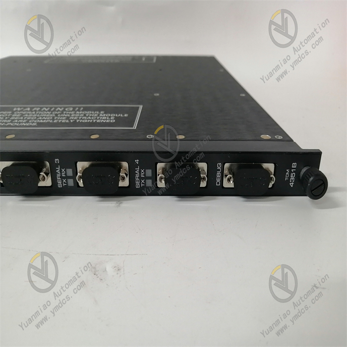
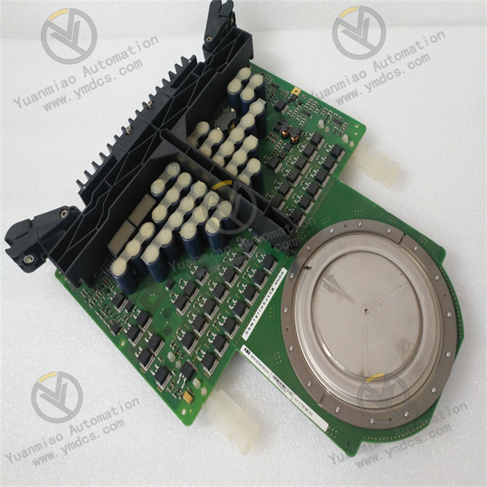
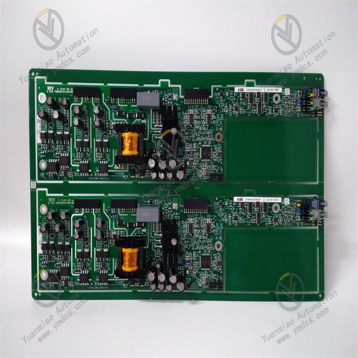
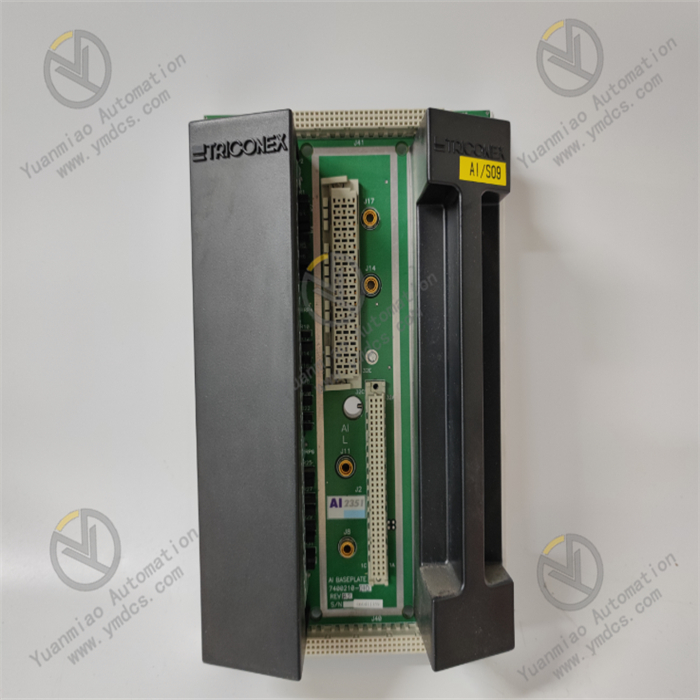
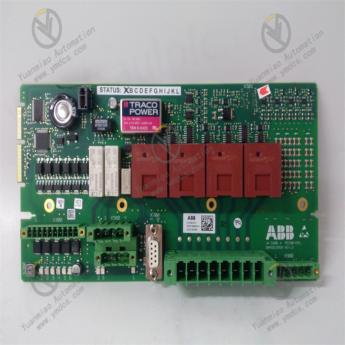
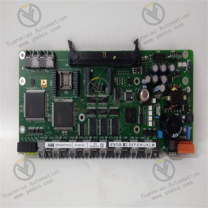
ABB 3ASC25H705/7 is a high‑performance digital main processing module for ABB high‑end industrial control systems. It belongs to the hardware portfolio of ABB Advant OCS and Freelance 900F distributed control systems, and serves as the core computation and control unit of DCS/PLC automation systems. Designed for complex logic computation, closed‑loop control, equipment interlocking, data processing and bus communication scheduling in large‑scale process industries, it undertakes critical tasks including core program execution, control‑command issuing, I/O data aggregation and process‑logic implementation, acting as the central hardware of automation control systems.
3ASC25H705/7 features high‑speed floating‑point computation, large‑capacity data buffer, multi‑protocol bus communication, real‑time task scheduling, hardware self‑diagnosis and redundant fault‑tolerant operation. It delivers fast response, high operational stability and excellent anti‑interference performance, supporting 24‑hour non‑stop automatic control in chemical, power, metallurgical, water‑treatment and building‑material industries. As an original ABB dedicated core spare part with no universal alternative, it is widely used for main‑controller replacement on legacy systems, control‑system hardware upgrade and core‑control‑unit capacity expansion. Its hardware architecture, communication protocols and underlying logic are fully compatible with supported systems. Configuration adaptation can be completed quickly for direct commissioning after replacement.
2. Functions and Features
2.1 Core Functions
High‑speed Core Logic Computation: Equipped with an industrial‑grade high‑performance main‑controller chip. It supports high‑speed execution of complex process‑control logic, PID closed‑loop regulation, sequence control, interlock logic and batch control. It can process massive I/O point data concurrently to ensure accurate and real‑time output of control commands under complex process conditions.
Centralised Scheduling of System‑wide I/O Data: Aggregates, computes, corrects and forwards global analogue and digital input‑output data. It uniformly manages the operating status of each I/O module and realises data interaction among field devices, process parameters and the supervisory host system.
Multi‑bus‑protocol‑compatible Communication: Natively supports ABB proprietary back‑plane bus and common industrial communication protocols. It enables high‑speed data exchange with I/O modules, host computers, HMI panels and third‑party automation devices, reliably implementing command distribution, status upload and parameter exchange to keep system communication links intact.
Real‑time Priority‑based Task Scheduling: Built‑in intelligent task scheduler prioritises emergency interlocks, closed‑loop regulation and routine monitoring. Critical process interlocks and precision‑control tasks are guaranteed to run first, preventing control lag and logic failure caused by task congestion.
Comprehensive Hardware Self‑diagnosis and Protection: Continuously monitors module supply voltage, chip temperature, bus‑communication status, program execution and buffer conditions. It accurately identifies hardware anomalies, program errors, communication outages and overload events, uploads real‑time alarms and activates fault‑protection mechanisms.
Native Redundant Fault‑tolerant Operation: Supports dual‑module hot‑standby redundancy. Primary and standby modules execute computations in parallel with real‑time data synchronisation. Bumpless automatic switchover occurs upon primary‑side failure without logic interruption or unintended equipment actuation, ensuring uninterrupted operation of critical process units.
Reliable Program Resident Operation: Equipped with industrial‑grade solid‑state storage for persistent retention of control programs, configuration parameters and process recipes. Parameters are preserved during power loss; operating status is automatically restored after power‑on, suiting cyclic continuous industrial production.
2.2 Product Features
High‑performance Low‑latency Computation: Adopts premium industrial computing architecture with powerful floating‑point capability and short instruction cycle. Ultra‑low system response latency suits high‑precision scenarios such as unit load variation, fine process tuning and dynamic closed‑loop control.
Industrial‑grade Wide‑temperature Stable Operation: Constructed with rugged industrial components. Computation remains stable without parameter drift across wide temperature ranges. It tolerates on‑site temperature fluctuation, minor vibration, dust and humidity, delivering low failure rates during long‑term continuous operation.
Robust Anti‑interference Hardware Design: Multi‑stage electromagnetic shielding, power‑supply filtering and surge‑suppression circuits mitigate industrial electromagnetic interference, ground‑potential difference, power fluctuation and high‑frequency radiation, avoiding computation abnormality, program crash and communication jitter.
High Compatibility with Minimal Commissioning: Fully compatible with ABB Advant OCS and Freelance 900F DCS families. Hardware interfaces, underlying protocols and configuration logic match perfectly. Replacing legacy main controllers requires no modification to system architecture or core configuration; only simple adaptation is needed for commissioning.
Safe Redundant Anti‑misoperation Mechanism: Implements fault latching, data validation and secondary‑command review. Output logic is automatically locked upon hardware anomaly or program error to prevent unintended equipment start‑stop, process‑parameter runaway and spurious interlock triggering.
3. Specifications
| Parameter Item | Technical Specification |
|---|---|
| Model | 3ASC25H705/7 |
| Device Type | DCS High‑performance Main Processing Module |
| Core Functions | System logic computation, I/O data scheduling, bus communication, redundant control, fault self‑diagnosis |
| Operating Architecture | Industrial‑grade high‑speed main‑controller architecture with priority‑driven multi‑task scheduling |
| Redundancy Mode | Dual‑module hot‑standby support with bumpless automatic switchover |
| Communication | ABB proprietary back‑plane bus & standard industrial protocols |
| Storage Feature | Parameters persist through power loss; automatic state restoration on power‑up |
| Ingress Protection | IP20 (standard indoor cabinet protection) |
| Power Supply | DC power from system cabinet back‑plane |
| Operating Temperature | 0 ℃ ~ +60 ℃ (standard industrial condition) |
| Ambient Humidity | 5%‑95%RH, non‑condensing |
| Explosion‑proof Rating | Standard non‑explosion‑proof version for cabinet‑internal installation |
| Installation | Slot‑mounted inside standard control cabinet |
| Applicable Systems | ABB Advant OCS / Freelance 900F DCS control systems |
4. Working Principle
ABB 3ASC25H705/7 main‑controller module follows a closed‑loop workflow: Data Collection & Aggregation → Core Logic Computation → Command Validation & Output → Bus Data Exchange → Real‑time Self‑diagnosis & Fault Tolerance.
After power‑on, the module completes power‑on self‑test, bus matching, program loading and parameter verification before entering normal operation. It continuously acquires field process data and device status signals uploaded by I/O modules, performing data filtering, correction, aggregation and storage.
Based on resident control programs and configuration logic, the module executes PID regulation, sequence control, process interlocks, equipment start‑stop logic and parameter calculation. Validated control commands are generated through algorithmic processing. After secondary data check and logic review, commands are transmitted via the back‑plane bus to corresponding output modules to drive on‑site control valves, actuators and variable‑frequency drives for stable closed‑loop process control. Meanwhile, it exchanges real‑time data with the supervisory HMI: uploading process values, equipment status, operation logs and fault messages, and receiving operator commands.
Hardware health, program execution, bus quality and data integrity are supervised throughout runtime. Upon detection of supply anomaly, chip over‑temperature, communication loss, program error or data corruption, fault‑latching protection is triggered, abnormal control logic is locked and alarms are sent to the host system. Under redundant configuration, the standby module synchronises all computation data and runtime states from the primary module. Millisecond‑level bumpless switchover takes place on primary failure to guarantee continuous, stable and safe operation of the automation system.
5. Application Scenarios
DCS Main‑controller for Chemical Processes: Core control unit for refinery, coal‑chemical and fine‑chemical plants. It executes logic computation, parameter regulation and equipment interlocks for reaction, distillation, heat‑exchange and separation units to stabilise continuous and fine chemical production.
Power‑plant Automation Systems: Main processing unit for boiler, turbine and auxiliary‑control systems in thermal power and cogeneration plants. It handles unit load regulation, peak‑shaving, equipment interlock protection and energy‑related calculation to support safe unit operation.
Oil‑gas Production Control Systems: Core computation unit for oilfields, gas fields, LNG facilities and long‑distance pipelines. It realises closed‑loop control of pressure, flow and level together with safety interlocks, suitable for remote unattended continuous production.
General Process‑industry Automation: Main controller for DCS/PLC systems in metallurgy, pharmaceutical, water‑treatment, building‑material and light‑industry sectors, covering closed‑loop process control, equipment coordination, safety interlocks and data monitoring.
Legacy ABB System Upgrade & Maintenance: Direct replacement for aged, faulty or under‑performing main controllers in existing ABB Advant OCS and Freelance 900F installations. No system‑architecture rework or full re‑configuration is required for rapid performance improvement and fault remediation.
6. Common Faults and Troubleshooting
6.1 No module alarm, no system logic execution, no equipment action
Fault Causes: Unloaded user program, lost configuration parameters, defective back‑plane bus communication, insufficient supply voltage, main‑controller chip malfunction.
Solutions: Verify stable back‑plane cabinet power supply. Inspect back‑plane bus interfaces and connections to resolve poor contact. Reload control program and configuration files, check parameter completeness. Power‑cycle the module for full initialisation. If symptoms persist, main‑controller hardware failure is confirmed; replace with original 3ASC25H705/7.
6.2 Sluggish system logic, delayed process control, slow parameter response
Fault Causes: Buffer overflow after long runtime, abnormal task scheduling, chip thermal throttling, degraded computation performance, excessive background program load.
Solutions: Improve cabinet ventilation and remove dust to resolve thermal throttling. Clear redundant background tasks and reset task scheduler. Power‑cycle to clear runtime buffers. Optimise configuration logic to reduce unnecessary computation load. Replace main‑controller if performance cannot be restored.
6.3 Frequent module communication alarms, intermittent I/O point dropout
Fault Causes: Ageing bus‑communication circuitry, poor back‑plane contact, protocol mismatch, data corruption due to electromagnetic interference.
Solutions: Improve cabinet earthing and shielding to suppress electromagnetic interference. Clean module gold‑fingers and back‑plane contacts, re‑seat firmly. Restart bus services and re‑negotiate communication protocols. Replace spare module if communication faults recur with all external causes eliminated.
6.4 Redundancy switchover failure, data desynchronisation between primary and standby
Fault Causes: Incorrect redundancy‑sync parameters, defective synchronisation circuitry, mismatched program revisions, faulty redundant link.
Solutions: Unify program versions and redundancy configuration for primary and standby modules. Inspect redundant sync bus and repair connection defects. Trigger manual synchronisation calibration. Replace faulty main‑controller if synchronisation cannot be recovered.
6.5 No power‑on alarm yet frequent module crash and program abort
Fault Causes: Degraded internal storage, corrupted program files, hardware intermittent connection, component ageing.
Solutions: Re‑flash control program to repair corrupted files. Stabilise cabinet power supply against voltage fluctuation. Optimise environmental conditions to avoid high temperature and humidity. Replace original module if crashes persist, indicating hardware degradation.